Home › Engine / Hybrid System › 1GR-FE FUEL › FUEL SYSTEM › 2009.08–2014.08
NM1440E _51 Engine / Hybrid System _056080 1GR-FE FUEL _0273698 FUEL SYSTEM UN GENERAL/CONTROL/DETAILS F

1GR-FE FUEL  FUEL SYSTEM  GENERAL/CONTROL/DETAILS  DETAILS  


CONSTRUCTION


a.

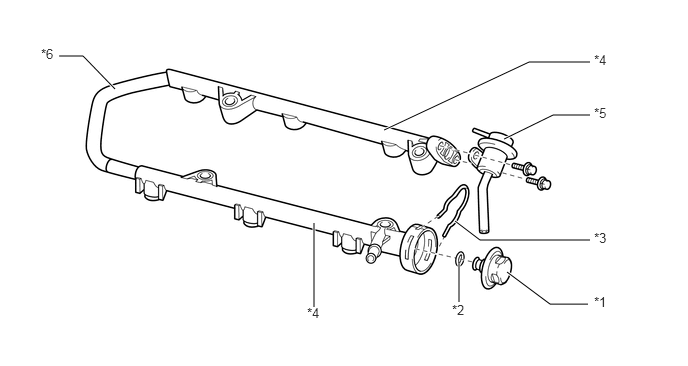
Fuel Delivery Pipe Sub-assembly

i.

Fuel delivery pipe sub-assemblies made of plastic are used to realize weight reduction.


ii.

The right and left fuel delivery pipe sub-assemblies are connected by a nylon tube.


iii.

The fuel pressure pulsation damper assembly is sealed with an O-ring and secured with a clip.


iv.

A nickel-phosphorus alloy coating is used on the fuel pressure regulator and the fuel pressure pulsation damper to prevent the E20 fuel from corroding them.
W102166E07
5.25,1.448 5.76,1.198 5.76,1.198 6.146,1.198 true 4,1.354 5.51,0.646 5.51,0.646 6.146,0.646 true 4.781,2.74 4.781,3.146 true 3.271,2.323 3.271,3.198 true 0.615,0.583 0.865,0.583 0.865,0.583 1.198,0.927 true 6.125,3.167 5.729,3.167 5.729,3.167 5.281,2.833 true 6.146,2.5 5,2.5 5,2.5 4.74,2.302 true 6.188,0.542 6.396,0.74 0.208,0.198 10 false *4 4.708,3.146 4.917,3.344 0.208,0.198 10 false *2 3.198,3.177 3.406,3.375 0.208,0.198 10 false *4 6.188,2.396 6.479,2.677 0.292,0.281 10 false *3 6.188,1.094 6.385,1.271 0.198,0.177 10 false *5 0.427,0.479 0.677,0.708 0.25,0.229 10 false *6 6.188,3.063 6.396,3.26 0.208,0.198 10 false *1

Text in Illustration
*1 Fuel Pressure Pulsation Damper Assembly *2 O-ring
*3 Clip *4 Fuel Delivery Pipe Sub-assembly
*5 Fuel Pressure Regulator Assembly *6 Nylon Tube


b.

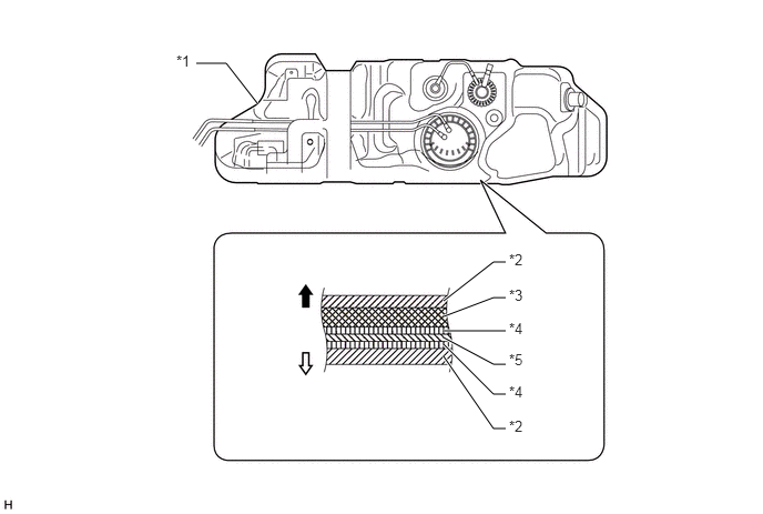
Fuel Tank Assembly

i.

The multi-layer plastic fuel tank consists of six layers of four types of materials, and one of those is a recyclable material to address environmental concerns.
U150609E03
4.167,2.823 4.635,2.458 4.635,2.458 4.75,2.458 true 4.167,3.104 4.75,3.104 true 4.167,3.167 4.635,3.417 4.635,3.417 4.75,3.417 true 4.167,3.229 4.635,3.698 4.635,3.698 4.75,3.698 true 4.167,3.344 4.635,4.021 4.635,4.021 4.75,4.021 true 4.167,2.969 4.635,2.792 4.635,2.792 4.75,2.792 true 2.417,0.969 2.125,0.594 2.125,0.594 1.844,0.594 true 4.781,2.354 5.042,2.563 0.26,0.208 10 false *2 1.656,0.49 1.917,0.677 0.26,0.188 10 false *1 4.781,2.688 5.052,2.917 0.271,0.229 10 false *3 4.781,3 5.083,3.198 0.302,0.198 10 false *4 4.781,3.292 5.073,3.51 0.292,0.219 10 false *5 4.781,3.594 5.063,3.792 0.281,0.198 10 false *4 4.781,3.917 5.135,4.146 0.354,0.229 10 false *2

Text in Illustration
*1 Fuel Tank Assembly *2 High Density Polyethylene (HDPE)
*3 Regrind Material *4 Adhesive
*5 Ethylene Vinyl Alcohol Copolymer (EVOH) - -
V100135

Fuel Tank Outside
V100136

Fuel Tank Inside


c.

Fuel Injector Assembly

i.

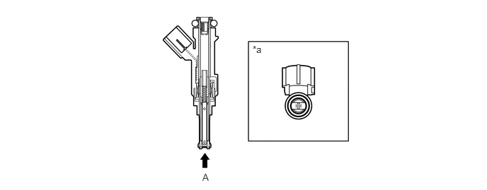
The fuel injector assembly is shaped to form a long nozzle. This shortens the distance from the fuel injector assembly to the intake valve, which prevents the fuel from adhering to the intake port walls and reduces HC exhaust emissions. Depending on the type of fuel that is used, a 12-hole type fuel injector assembly is provided.


ii.

The magnetic circuit, jet orifice and load spring inside the fuel injector are optimized for E20 fuel.
U150610E02
3.719,0.646 3.99,0.885 0.271,0.24 10 false *a 2.979,2.531 3.302,2.771 0.323,0.24 10 false A

Text in Illustration
*a View A - -


d.

Fuel Suction with Pump and Gauge Tube Assembly

i.

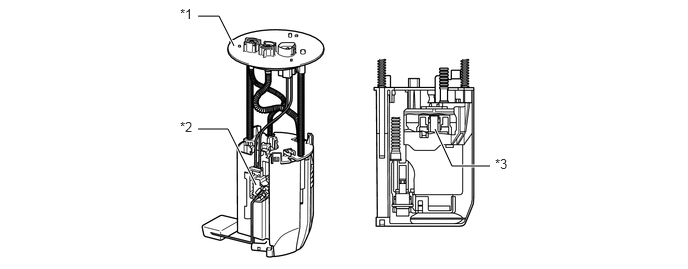
A compact fuel suction with pump and gauge tube assembly is used. Its basic components are a fuel pump, a fuel filter, and a fuel sender gauge assembly.
W102186E02
2.063,0.167 2.281,0.167 2.281,0.167 2.438,0.479 true 2.063,1.344 2.375,1.344 2.375,1.344 2.667,1.927 true 4.531,1.344 4.708,1.729 4.708,1.729 5.104,1.729 true 1.875,0.063 2.125,0.323 0.25,0.26 10 false *1 1.875,1.24 2.125,1.5 0.25,0.26 10 false *2 5.156,1.625 5.406,1.885 0.25,0.26 10 false *3

Text in Illustration
*1 Suction with Pump and Gauge Tube Assembly *2 Fuel Sender Gauge Assembly
*3 Fuel Pump - -