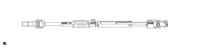
STEERING COLUMN STEERING COLUMN SYSTEM GENERAL/CONTROL/DETAILS DETAILS
CONSTRUCTION
Manual Tilt and Telescopic Mechanism
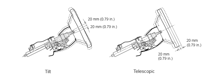
The manual tilt and telescopic mechanism allows adjustment of the steering wheel position in the vertical and longitudinal (extending and retracting) directions through lever operation. This provides the driver with the most comfortable driving position.
The manual tilt and telescopic mechanism is locked using the tilt and telescopic lever.
The tilt adjustment range is 40.0 mm (1.57 in.).
The telescopic adjustment range is 40.0 mm (1.57 in.).
Energy Absorbing Mechanism
The energy absorbing mechanism mainly consists of the breakaway bracket, steering intermediate shaft assembly, steering intermediate shaft sub-assembly, and column tube. The steering column assembly is mounted on the instrument panel reinforcement via a breakaway bracket. The steering column assembly and the steering gear assembly are connected with a contractile intermediate shaft.
When the steering gear assembly moves during a collision (primary collision), the steering intermediate shaft sub-assembly contracts, thus helping reduce the possibility of the steering column assembly and the steering wheel protruding into the cabin.
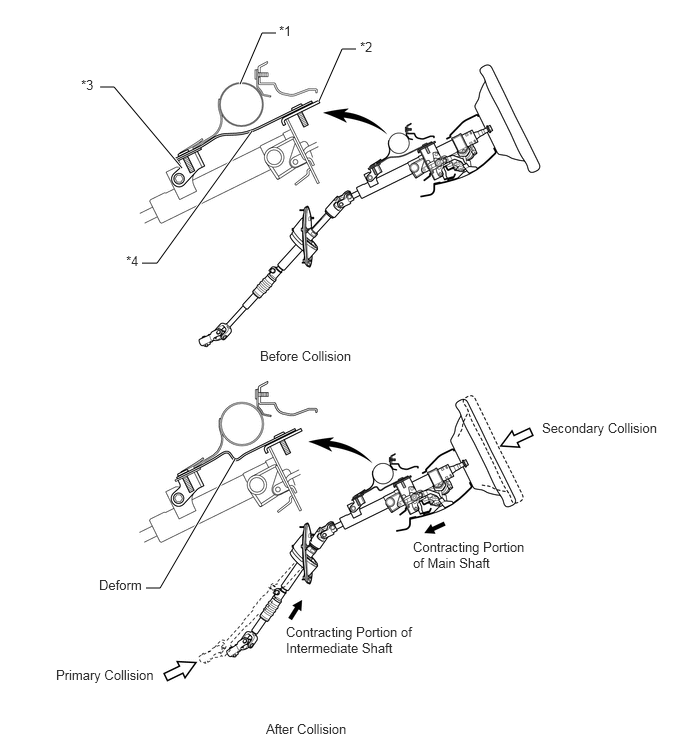
| *1 | Instrument Panel Reinforcement | *2 | Breakaway Bracket |
| *3 | Lower Bracket | *4 | Energy Absorbing Plate |
When a collision impact is transmitted to the steering wheel (secondary collision), the steering wheel and the airbag help absorb the impact.
The breakaway bracket and the instrument panel reinforcement separate, and the column tube contracts.
By using a permanently expandable and contractible steering intermediate shaft assembly and a steering intermediate shaft sub-assembly that deforms and contracts during collisions, safety during collisions is ensured and a smooth steering feeling is achieved.