1GR-FE FUEL FUEL INJECTOR INSTALLATION
PROCEDURE

 23250
1.INSTALL FUEL INJECTOR ASSEMBLY
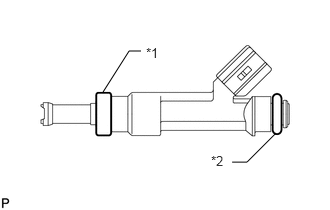
Install a new injector vibration insulator to each fuel injector assembly.
| *1 | New Insulator |
| *2 | New O-Ring |
Apply a light coat of spindle oil or gasoline to new O-rings and install one to each fuel injector assembly.
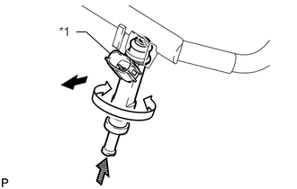
Install the 6 fuel injector assemblies.
While turning each fuel injector assembly left and right, install it to the fuel delivery pipe sub-assembly.
| *1 | Connector |

|
Outward |

|
Turn |

|
Push |
Position the fuel injector assemblies with the connectors facing outward.
23807
2.INSTALL FUEL DELIVERY PIPE SUB-ASSEMBLY
Place the fuel delivery pipe sub-assembly together with the 6 fuel injector assemblies on the intake manifold.
Temporarily install the 6 bolts, which are used to hold the fuel delivery pipe sub-assembly in place, to the intake manifold.
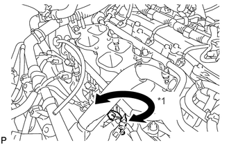
Check that the fuel injector assemblies rotate smoothly.
| *1 | Turn |
If the fuel injector assemblies do not rotate smoothly, replace the O-ring of any fuel injector assembly that does not rotate smoothly.
Position the fuel injector assemblies with the connectors facing outward.
Tighten the 6 bolts.
- Torque:
- 21 N*m (214 kgf*cm, 15 ft.*lbf)
Connect the 6 fuel injector connectors.
23802B
3.CONNECT NO. 2 FUEL PIPE SUB-ASSEMBLY
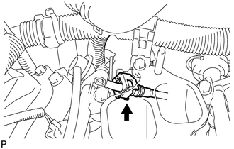
Connect the No. 2 fuel pipe sub-assembly (See page Engine / Hybrid System>1GR-FE FUEL>FUEL SYSTEM>PRECAUTION).
23801P
4.CONNECT NO. 1 FUEL PIPE SUB-ASSEMBLY
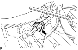
Connect the No. 1 fuel pipe sub-assembly (See page Engine / Hybrid System>1GR-FE FUEL>FUEL SYSTEM>PRECAUTION).
11181A
5.INSTALL REAR CYLINDER HEAD COVER
Temporarily install the rear cylinder head cover with the 3 bolts.
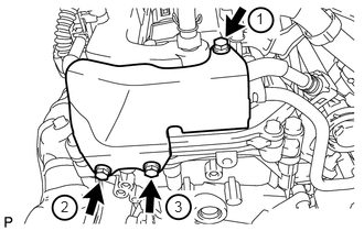
Tighten the 3 bolts in the sequence shown in the illustration.
- Torque:
- 9.0 N*m (92 kgf*cm, 80 in.*lbf)
17129
6.INSTALL INTAKE AIR SURGE TANK
Install the intake air surge tank (See page Engine / Hybrid System>1GR-FE INTAKE / EXHAUST>INTAKE MANIFOLD>INSTALLATION).
7.INSPECT FOR FUEL LEAK
Make sure that there are no fuel leaks after performing maintenance on the fuel system.
Connect the GTS to the DLC3.
Turn the ignition switch to ON and turn the GTS on.
- NOTICE:
-
Do not start the engine.
Enter the following menus: Powertrain / Engine and ECT / Active Test / Control the Fuel Pump / Speed.
Check that there are no leaks from the fuel system.
If there are fuel leaks, repair or replace parts as necessary.
Turn the ignition switch off.
Disconnect the GTS from the DLC3.