1GR-FE EMISSION CONTROL CANISTER INSTALLATION
PROCEDURE

 77740
1.INSTALL CANISTER ASSEMBLY (w/ Secondary Air Injection System)
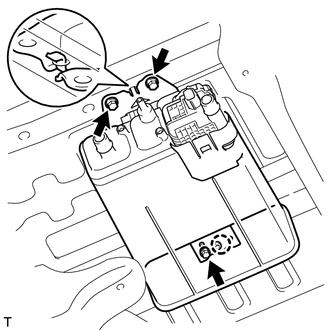
Attach the claw and install the canister assembly with the 3 bolts.
- Torque:
- 20 N*m (204 kgf*cm, 15 ft.*lbf)
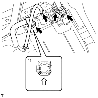
Connect the vent line hose.
| *1 | Vent Line Hose |

|
Push |
Push the hose into the port and push the retainer to lock it.
- NOTICE:
- ·
Check for damage or foreign objects on the connected part.
·After connecting, check that the vent hose and valve are securely connected by pulling on them.
Connect the air inlet line hose.
- NOTICE:
- ·
Check for damage or foreign objects on the connected part.
·After connecting, check that the vent hose and valve are securely connected by pulling on them.
Connect the purge line hose.
Connect the canister pump module connector.
2.INSTALL SPARE TIRE (w/ Secondary Air Injection System)
77704
3.INSTALL CANISTER (w/o Secondary Air Injection System)
Install the canister to the bracket.
Connect the air inlet line hose to the canister.
Connect the vent line hose to the canister.
Connect the purge line hose to the canister.