1GR-FE EMISSION CONTROL CANISTER INSPECTION
PROCEDURE

 77704
1.INSPECT CANISTER (w/o Secondary Air Injection System)
Visually check the canister for cracks or damage.
If cracks or damage is found, replace the canister.
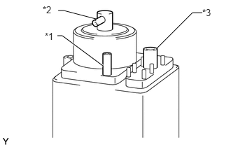
Using SST, inspect the canister.
- SST
- 09992-00242
- OK:
Measurement Condition Specified Condition Ports B and C closed, vacuum applied to port A [1.96 kPa (15 mmHg, 0.579 in.Hg)] No leak Port C closed, vacuum applied to port A [1.96 kPa (15 mmHg, 0.579 in.Hg)] Air flows from port B Port C closed, air blow into port A [4.71 kPa (0.05 kgf/cm2, 0.7 psi)] Air flows from port B Air blow into port A [4.71 kPa (0.05 kgf/cm2, 0.7 psi)] Air flows from both ports B and C
| *1 | Port A |
| *2 | Port B |
| *3 | Port C |
If the result is not as specified, replace the canister.
77740
2.INSPECT CANISTER ASSEMBLY (w/ Secondary Air Injection System)
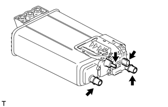
Visually check the canister assembly for cracks or damage.
If cracks or damage is found, replace the canister assembly.
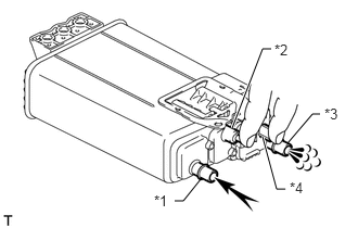
Check the canister operation.
With the purge port and connector closed, blow 5 kPa (0.1 kgf/cm2, 0.7 psi) of air into the vent port, and check that air flows from the air inlet port.
| *1 | Vent Port |
| *2 | Purge Port |
| *3 | Air Inlet Port |
| *4 | Connector |

|
Air |
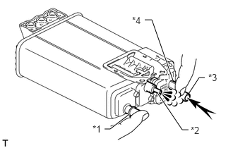
With the vent port and connector closed, blow 5 kPa (0.1 kgf/cm2, 0.7 psi) of air into the air inlet port, and check that air flows from the purge port.
| *1 | Vent Port |
| *2 | Purge Port |
| *3 | Air Inlet Port |
| *4 | Connector |
|
|
Air |
If the result is not as specified, replace the canister assembly.
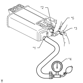
Check for air leaks.
Connect a pressure gauge to the vent port of the canister.
| *1 | Vent Port |
| *2 | Purge Port |
| *3 | Air Inlet Port |
| *4 | Pressure Gauge |
| *5 | Connector |
With the purge port, air inlet port and connector closed, apply 19.6 kPa (0.2 kgf/cm2, 2.81 psi) of pressurized air into the vent port, and then confirm that pressure is retained for 1 minute.
If the result is not as specified, replace the canister assembly.