RM1440E
_51
Engine / Hybrid System
_056127
1GR-FE EMISSION CONTROL
_0273898
PURGE VALVE
G
1GR-FE EMISSION CONTROL PURGE VALVE INSPECTION
PROCEDURE

 25860
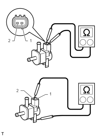
1.INSPECT PURGE VSV
a.
0.958,1.406 0.885,1.406
0.885,1.406 0.74,0.823
true
0.417,1.406 0.49,1.406
0.49,1.406 0.604,0.823
true
0.708,3.115 0.823,3.115
0.823,3.115 1.156,3.406
true
1.208,3.427 1.563,3.25
1.563,3.25 1.646,3.25
true
0.281,1.313 0.406,1.479
0.125,0.167
10
false
2
1.021,1.313 1.146,1.479
0.125,0.167
10
false
1
0.563,3.031 0.688,3.198
0.125,0.167
10
false
2
1.698,3.146 1.823,3.313
0.125,0.167
10
false
1
Measure the resistance according to the value(s) in the table below.
- Standard Resistance:
Tester Connection Condition Specified Condition 1 - 2 20°C (68°F) 23 to 26 Ω 1 - Body ground Always 10 MΩ or higher 2 - Body ground Always 10 MΩ or higher
- HINT:
-
When measuring the coil resistance make sure that the surface temperature of the purge VSV is 20°C.
b.
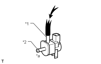
Check the operation of the purge VSV.
i.
0.948,1.417 1.052,1.417
1.052,1.417 1.271,1.677
false
1.031,0.792 1.135,0.792
1.135,0.792 1.573,1.26
false
0.854,0.729 1.031,0.906
0.177,0.177
10
false
*1
0.771,1.354 0.948,1.531
0.177,0.177
10
false
*2
1.229,1.823 1.427,1.99
0.198,0.167
10
false
*a
Check that air does not flow from port E to port F.
| *1 | Port E |
| *2 | Port F |
| *a | Does not flow |
ii.
1.583,0.063 1.844,0.229
0.26,0.167
10
false
*1
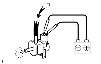
Apply battery voltage to the connector and check the VSV operation.
- OK:
Measurement Condition Specified Condition Battery positive (+) → Terminal 1
Battery negative (-) → Terminal 2Air flows from port E to port F
| *1 | Air |
If the result is not as specified, replace the purge VSV.