Home › Engine / Hybrid System › 1GR-FE EMISSION CONTROL › AIR PUMP › from 2014.08
RM1440E _51 Engine / Hybrid System _056127 1GR-FE EMISSION CONTROL _0273901 AIR PUMP A

1GR-FE EMISSION CONTROL  AIR PUMP  INSTALLATION  


PROCEDURE

Hide 17610C 1.INSTALL AIR PUMP ASSEMBLY

a.
A388118E01
0.865,0.563 1.219,0.167 1.219,0.167 1.427,0.167 true 1.01,0.677 1.146,0.542 1.146,0.542 1.427,0.542 true 1.01,0.969 1.146,0.833 1.146,0.833 1.427,0.833 true 1.479,0.104 1.792,0.302 0.313,0.198 10 false *1 1.49,0.458 1.802,0.656 0.313,0.198 10 false *2 1.49,0.75 1.802,0.948 0.313,0.198 10 false *3

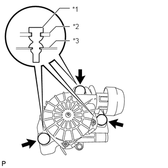
Attach the 3 fittings of the air pump insulators to install the air pump assembly to the air pump bracket.

Text in Illustration
*1 Air Pump Insulator
*2 Air Pump Assembly
*3 Air Pump Bracket


b.

Attach the wire harness clamp and air pump connector clamp.


c.

Install the air pump assembly with bracket with the 3 bolts.

Torque:
20 N*m (204 kgf*cm, 15 ft.*lbf)


d.

Connect the air pump connector and attach the wire harness clamp.


Hide 17341 2.INSTALL NO. 1 AIR INJECTION SYSTEM HOSE

a.

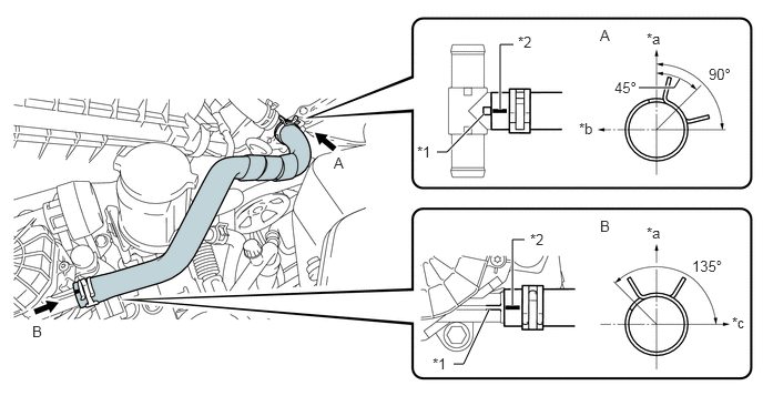
Connect the No. 1 air injection system hose so that its paint marks align with the projections of the air tube assembly and air pump assembly as shown in the illustration.
A289617E03
4.698,1.031 4.698,0.417 4.698,0.417 4.823,0.417 true 4.542,1.073 4.198,1.427 4.198,1.427 4.104,1.427 true 4.813,2.865 4.813,2.25 4.813,2.25 4.927,2.25 true 4.594,2.906 4.354,3.417 4.354,3.417 4.26,3.417 true 6.385,0.74 6.333,0.823 6.333,0.823 6,0.823 true 5.635,0.25 5.833,0.427 0.198,0.177 10 false A 3.135,1.448 3.333,1.625 0.198,0.177 10 false A 5.635,2.042 5.833,2.219 0.198,0.177 10 false B 0.302,3.031 0.5,3.208 0.198,0.177 10 false B 4.063,3.333 4.281,3.531 0.219,0.198 10 false *1 3.917,1.344 4.188,1.594 0.271,0.25 10 false *1 4.979,2.167 5.25,2.417 0.271,0.25 10 false *2 4.865,0.313 5.135,0.563 0.271,0.25 10 false *2 6.5,2.417 6.958,2.625 0.458,0.208 10 false 135° 6.656,0.615 6.99,0.823 0.333,0.208 10 false 90° 6.073,0.281 6.292,0.479 0.219,0.198 10 false *a 6.073,2.104 6.292,2.302 0.219,0.198 10 false *a 5.438,1.125 5.656,1.323 0.219,0.198 10 false *b 6.875,2.948 7.094,3.146 0.219,0.198 10 false *c 5.771,0.74 6.104,0.948 0.333,0.208 10 false 45°

Text in Illustration
*1 Projection *2 Paint Mark
*a Upper *b RH Side
*c Front - -

HINT:
·

Make sure the paint mark of the No. 1 air injection system hose is facing upward.

·

Make sure the direction of the hose clamp is as shown in the illustration.


Hide 17613 3.INSTALL AIR PUMP COVER

a.
A273789E01
2.797,1.454 2.952,1.617 0.156,0.163 10 *1 2.791,1.549 2.636,1.549 2.636,1.549 2.275,1.769 false

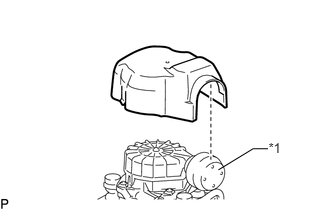
Install the air pump cover with the 3 claws.

Text in Illustration
*1 Inlet

HINT:

Make sure the inlet of the air pump cover is oriented correctly and completely attached when installing the air pump cover.