RM1440E
_51
Engine / Hybrid System
_056132
CRUISE CONTROL
_0273923
CRUISE CONTROL SYSTEM
U
CRUISE CONTROL CRUISE CONTROL SYSTEM TERMINALS OF ECM
CHECK ECM
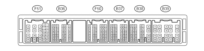
1.208,0.219 1.698,0.438
0.49,0.219
10
false
F51
2.042,0.219 2.417,0.438
0.375,0.219
10
false
B36
3.323,0.219 3.698,0.448
0.375,0.229
10
false
F50
4.073,0.219 4.427,0.406
0.354,0.188
10
false
B37
4.792,0.219 5.115,0.417
0.323,0.198
10
false
B38
5.698,0.219 6.125,0.427
0.427,0.208
10
false
B39
a.
Disconnect the B38, F50 and F51 ECM connectors.
b.
Measure the voltage and resistance according to the value(s) in the table below.
| Terminal No. (Symbol) | Wiring Color | Terminal Description | Condition | Specified Condition |
|---|---|---|---|---|
| F51-24 (BATT) - Body ground | L - Body ground | Power source circuit | Always | 11 to 14 V |
| F50-21 (IGSW) - Body ground | W - Body ground | IG power source circuit | Ignition switch ON | 11 to 14 V |
| Ignition switch off | Below 1 V | |||
| F51-8 (ST1-) - Body ground | B - Body ground | Stop light switch signal circuit | Ignition switch ON, brake pedal released | 11 to 14 V |
| Ignition switch ON, brake pedal depressed | Below 1 V | |||
| F50-18 (STP) - Body ground | V - Body ground | Stop light switch signal circuit | Brake pedal depressed | 11 to 14 V |
| Brake pedal released | Below 1 V | |||
| F50-11 (CCS) - Body ground | B - Body ground | Cruise control switch circuit | Cruise control switch on | Below 2.5 Ω |
| Cruise control switch off | 1 MΩ or higher | |||
| +RES switch held on | 235 to 245 Ω | |||
| -SET switch held on | 617 to 643 Ω | |||
| CANCEL switch held on | 1509 to 1571 Ω | |||
| B38-12 (E1) - Body ground | BR - Body ground | Ground | Always | Below 1 Ω |
If the result is not as specified, there may be a malfunction on the wire harness side.
c.
Reconnect the B38, F50 and F51 ECM connectors.
d.
Measure the voltage according to the value(s) in the table below.
| Terminal No. (Symbol) | Wiring Color | Terminal Description | Condition | Specified Condition |
|---|---|---|---|---|
| B36-27 (D) - Body ground | B - Body ground | Park/neutral position switch signal | Ignition switch ON, shift lever in D | 11 to 14 V |
| Ignition switch ON, shift lever not in D | Below 1 V | |||
| B36-29 (N) - Body ground | G - Body ground | Park/neutral position switch signal | Ignition switch ON, shift lever in N | 11 to 14 V |
| Ignition switch ON, shift lever not in N | Below 1 V | |||
| B36-28 (R) - Body ground | R - Body ground | Park/neutral position switch signal | Ignition switch ON, shift lever in R | 11 to 14 V |
| Ignition switch ON, shift lever not in R | Below 1 V | |||
| B36-35 (P) - Body ground | L - Body ground | Park/neutral position switch signal | Ignition switch ON, shift lever in P | 11 to 14 V |
| Ignition switch ON, shift lever not in P | Below 1 V | |||
| F50-24 (S) - Body ground | V - Body ground | Transmission control switch circuit | Ignition switch ON, shift lever in S | 11 to 14 V |
| Ignition switch ON, shift lever not in S | Below 1 V | |||
| F50-16 (SFTU) - Body ground | GR - Body ground | Transmission control switch circuit | Ignition switch ON, shift lever in S → shift lever moved to "+" | 11 to 14 V → Below 1 V |
| F50-22 (SFTD) - Body ground | LG - Body ground | Transmission control switch circuit | Ignition switch ON, shift lever in S → shift lever moved to "-" | 11 to 14 V → Below 1 V |
If the result is not as specified, the ECM may be malfunctioning.