A750F AUTOMATIC TRANSMISSION / TRANSAXLE TRANSMISSION CONTROL CABLE INSTALLATION
PROCEDURE

 33820B
1.INSTALL TRANSMISSION CONTROL CABLE ASSEMBLY
Insert the transmission control cable from the vehicle outside, and attach the 3 claws of the cable retainer.
Install the 2 nuts.
- Torque:
- 5.5 N*m (56 kgf*cm, 49 in.*lbf)
Connect the transmission control cable to the transmission control cable bracket with a new clip, and connect the cable end to the control shaft lever with the nut.
- Torque:
- 14 N*m (143 kgf*cm, 10 ft.*lbf)
Connect the transmission control cable support with the 2 nuts.
- Torque:
- 5.5 N*m (56 kgf*cm, 49 in.*lbf)
Turn the socket of the transmission control cable 180° counterclockwise. While holding the socket in place, push in the lock piece until the lock piece clicks twice.
- NOTICE:
-
Do not over-rotate the socket as it will come off the internal spring and the transmission control cable will not be reusable.
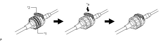
| *1 | Socket | *2 | Lock Piece |
| *a | Push in | - | - |
- HINT:
-
If the lock piece cannot be pushed in, slightly turn the socket clockwise and then push in the lock piece again.
Install the outer part of the transmission control cable to the shift lever retainer. Check that the socket and lock piece are positioned at original position.
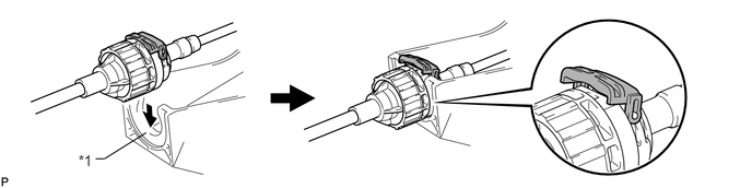
| *1 | Shift Lever Retainer | - | - |
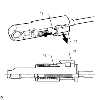
Slide the slider in the direction shown in the illustration and pull out the lock piece.
| *1 | Slider |
| *2 | Lock Piece |
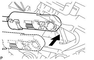
Connect the end of the cable to the shift lever.
- NOTICE:
- ·
Make sure that the lock piece is pulled up.
·Push on the end of the cable all the way to the base of the pin.
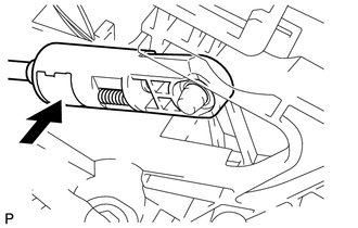
Push the lock piece into the adjuster case and lock it.
- NOTICE:
-
Make sure that the lock piece is completely locked by the slider.
58910C
2.INSTALL REAR CONSOLE BOX ASSEMBLY
Install the console box (See page Vehicle Interior>INTERIOR PANELS / TRIM>FRONT CONSOLE BOX>INSTALLATION).