VF4BM TRANSFER / 4WD / AWD TRANSFER ASSEMBLY INSPECTION
PROCEDURE

 36211
1.INSPECT TRANSFER INPUT SHAFT
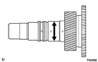
Using a micrometer, measure the outer diameter of the input shaft journal surface.
- Minimum diameter:
47.59 mm (1.88 in.)
If the outer diameter is less than the minimum, replace the input shaft.
2.INSPECT PLANETARY PINION GEAR THRUST CLEARANCE
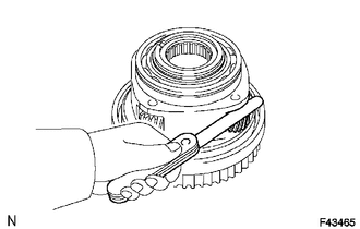
Using a feeler gauge, measure the thrust clearance of the planetary pinion gear.
- Standard clearance:
0.11 to 0.84 mm (0.00434 to 0.0330 in.)
- Maximum clearance:
0.84 mm (0.0330 in.)
If the clearance is more than the maximum, replace the planetary gear.
3.INSPECT PLANETARY PINION GEAR RADIAL CLEARANCE
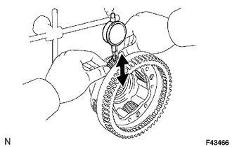
Using a dial indicator, measure the radial clearance of the planetary pinion gear.
- Standard clearance:
0.009 to 0.038 mm (0.000355 to 0.00149 in.)
- Maximum clearance:
0.038 mm (0.00149 in.)
If the clearance is more than the maximum, replace the planetary gear.
36231
4.INSPECT TRANSFER OUTPUT SHAFT REAR
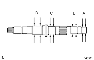
Using a micrometer, measure the outer diameter of the output shaft rear journal surfaces.
- Standard diameter:
- Journal A:
27.98 to 27.99 mm (1.1015 to 1.1019 in.)
- Journal B:
31.98 to 32.00 mm (1.2591 to 1.2598 in.)
- Journal C:
34.98 to 35.00 mm (1.3772 to 1.3779 in.)
- Journal D:
36.98 to 37.00 mm (1.4560 to 1.4566 in.)
- Minimum diameter:
- Journal A:
27.98 mm (1.1015 in.)
- Journal B:
31.98 mm (1.2591 in.)
- Journal C:
34.98 mm (1.3772 in.)
- Journal D:
36.98 mm (1.4560 in.)
If the outer diameter is less than the minimum, replace the rear output shaft.
36235
5.INSPECT TRANSFER HIGH AND LOW CLUTCH SLEEVE AND NO. 2 TRANSFER GEAR SHIFT FORK CLEARANCE
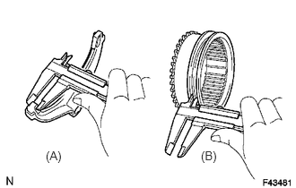
Using a vernier caliper, measure the thickness of the shift fork claw.
- Standard thickness (A):
10 mm (0.394 in.)
Using a vernier caliper, measure the width of the groove of the high and low clutch sleeve.
- Standard width (B):
10.5 mm (0.413 in.)
Calculate the clearance between the high and low clutch sleeve and shift fork.
- Standard clearance (B) - (A):
0.26 to 0.84 mm (0.0103 to 0.0330 in.)
- Maximum clearance (B) - (A):
0.84 mm (0.0330 in.)
If the clearance is more than the maximum, replace the high and low clutch sleeve or shift fork.
36236
6.INSPECT FRONT DRIVE CLUTCH SLEEVE AND CENTER DIFFERENTIAL LOCK FORK SUB-ASSEMBLY CLEARANCE
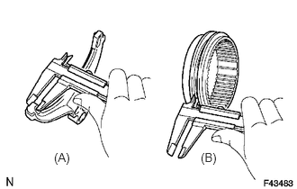
Using a vernier caliper, measure the thickness of the center differential lock fork claw.
- Standard thickness (A):
10 mm (0.394 in.)
Using a vernier caliper, measure the width of the groove of the front drive clutch sleeve.
- Standard width (B):
10.5 mm (0.413 in.)
Calculate the clearance between the front drive clutch sleeve and differential lock fork.
- Standard clearance (B) - (A):
0.26 to 0.84 mm (0.0103 to 0.0330 in.)
- Maximum clearance (B) - (A):
0.84 mm (0.0330 in.)
If the clearance is more than the maximum, replace the front drive clutch sleeve or differential lock fork.
7.INSPECT CENTER DIFFERENTIAL CASE AND TRANSFER HIGH AND LOW CLUTCH SLEEVE
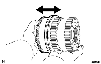
Check that the splines of the clutch sleeve are not worn.
Install the clutch sleeve to the center differential case and check that the clutch sleeve moves smoothly.
8.INSPECT CENTER DIFFERENTIAL CASE AND FRONT DRIVE CLUTCH SLEEVE
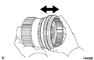
Check that the splines of the clutch sleeve are not worn.
Install the clutch sleeve to the center differential case and check that the clutch sleeve moves smoothly.