RM1440E
_52
Drivetrain
_056135
VF4BM TRANSFER / 4WD / AWD
_0273959
TRANSFER SYSTEM
U
VF4BM TRANSFER / 4WD / AWD TRANSFER SYSTEM TERMINALS OF ECU
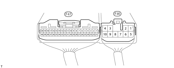
CHECK FOUR WHEEL DRIVE CONTROL ECU
2.698,0.5 3,0.667
0.302,0.167
10
false
F47
4.719,0.479 5.021,0.646
0.302,0.167
10
false
F46
a.
Measure the voltage and resistance according to the value(s) in the table below.
| Terminal No. (Symbol) | Wiring Color | Terminal Description | Condition | Specified Condition |
|---|---|---|---|---|
| F47-1 (HL1) - F46-4 (GND) | GR - W-B | High-low transfer shift actuator limit switch | Ignition switch ON
Transfer position switch H4F or H4L |
10.5 to 14 V |
| Ignition switch ON
Transfer position switch L4L |
Below 1.5 V | |||
| F47-2 (HL2) - F46-4 (GND) | LG - W-B | High-low transfer shift actuator limit switch | Ignition switch ON
Transfer position switch H4F or H4L |
Below 1.5 V |
| Ignition switch ON
Transfer position switch L4L |
10.5 to 14 V | |||
| F47-6 (TL1) - F46-4 (GND) | W-B - W-B | Transfer operating switch mode selection signal | Always | Below 1 Ω |
| F47-7 (TL2) - F46-4 (GND) | L - W-B | Multi mode transfer shift actuator limit switch | Ignition switch ON
Transfer position switch H4L or L4L |
Below 1.5 V |
| Ignition switch ON
Transfer position switch H4F |
10.5 to 14 V | |||
| F47-8 (TL3) - F46-4 (GND) | R - W-B | Multi mode transfer shift actuator limit switch | Ignition switch ON
Transfer position switch H4L or L4L |
10.5 to 14 V |
| Ignition switch ON
Transfer position switch H4F |
Below 1.5 V | |||
| F47-11 (2-4) - F46-4 (GND) | W - W-B | Transfer position switch | Ignition switch ON
Transfer position switch H4F or H4L |
Below 1.5 V |
| Ignition switch ON
Transfer position switch L4L |
10.5 to 14 V | |||
| F47-13 (LO) - F46-4 (GND) | B - W-B | Transfer position switch | Ignition switch ON
Transfer position switch H4F |
10.5 to 14 V |
| Ignition switch ON
Transfer position switch H4L or L4L |
Below 1.5 V | |||
| F47-14 (P1) - F46-4 (GND) | W - W-B | Multi mode transfer shift actuator
Center differential lock position detection switch |
Ignition switch ON
Transfer position switch H4F |
9.5 to 14 V |
| Ignition switch ON
Transfer position switch H4L or L4L |
Below 1.5 V | |||
| F47-19 (CANH) - F46-4 (GND) | G - W-B | CAN communication line | Ignition switch ON | Pulse generation (See waveform 1) |
| F47-20 (CANL) - F46-4 (GND) | W - W-B | CAN communication line | Ignition switch ON | Pulse generation (See waveform 2) |
| F47-21 (L4) - F46-4 (GND) | R - W-B | Transfer L4 signal | Ignition switch ON
Transfer position switch H4F or H4L |
10 to 14 V |
| Ignition switch ON
Transfer position switch L4L |
Below 1.5 V | |||
| F46-2 (HM1) - F46-4 (GND) | B - W-B | High-low transfer shift actuator motor | Ignition switch ON
Transfer position switch H4L → L4L (During operation of high-low transfer shift actuator motor from HIGH to LOW) |
10 to 14 V |
| Ignition switch ON
Transfer position switch H4L → L4L (High-low transfer shift actuator motor stopped) |
Below 1.5 V | |||
| F46-3 (IG) - F46-4 (GND) | R - W-B | IG power | Ignition switch ON | 11 to 14 V |
| F46-4 (GND) - Body ground | W-B - Body ground | Ground | Always | Below 1 Ω |
| F46-6 (HM2) - F46-4 (GND) | W - W-B | High-low transfer shift actuator motor | Ignition switch ON
Transfer position switch L4L → H4L (During operation of high-low transfer shift actuator motor from LOW to HIGH) |
10 to 14 V |
| Ignition switch ON
Transfer position switch L4L → H4L (High-low transfer shift actuator motor stopped) |
Below 1.5 V | |||
| F46-7 (TM2) - F46-4 (GND) | V - W-B | Multi mode transfer shift actuator motor | Ignition switch ON
Transfer position switch H4L → H4F (During operation of multi mode transfer shift actuator motor from LOCK to FREE) |
10 to 14 V |
| Ignition switch ON
Transfer position switch H4L → H4F (Multi mode transfer shift actuator motor stopped) |
Below 1.5 V | |||
| F46-8 (TM1) - F46-4 (GND) | P - W-B | Multi mode transfer shift actuator motor | Ignition switch ON
Transfer position switch H4F → H4L (During operation of multi mode transfer shift actuator motor from FREE to LOCK) |
10 to 14 V |
| Ignition switch ON
Transfer position switch H4F → H4L (Multi mode transfer shift actuator motor stopped) |
Below 1.5 V |
b.
0.083,0.063 0.396,0.26
0.313,0.198
10
false
*1
2.969,1.417 3.323,1.635
0.354,0.219
10
false
GND
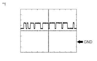
Using an oscilloscope, check waveform 1.
| Item | Content |
|---|---|
| Terminal No. (Symbols) | F47-19 (CANH) - F46-4 (GND) |
| Tool setting | 1 V/DIV., 10 μsec./DIV. |
| Condition | Engine stopped and ignition switch ON |
| *1 | Waveform 1 |
- HINT:
-
The waveform varies depending on the CAN communication signal.
c.
0.083,0.052 0.396,0.25
0.313,0.198
10
false
*1
2.969,1.375 3.375,1.646
0.406,0.271
10
false
GND
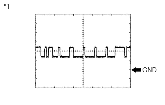
Using an oscilloscope, check waveform 2.
| Item | Content |
|---|---|
| Terminal No. (Symbols) | F47-20 (CANL) - F46-4 (GND) |
| Tool setting | 1 V/DIV., 10 μsec./DIV. |
| Condition | Engine stopped and ignition switch ON |
| *1 | Waveform 2 |
- HINT:
-
The waveform varies depending on the CAN communication signal.