RM1440E
_55
Steering
_056147
POWER ASSIST SYSTEMS
_0274019
POWER STEERING SYSTEM
J
POWER ASSIST SYSTEMS POWER STEERING SYSTEM IG Power Source Circuit
DESCRIPTION
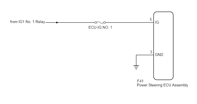
When the ignition switch is turned to ON, the IG power source circuit supplies positive (+) voltage to the power steering ECU assembly.
WIRING DIAGRAM
4.99,2.885 5.438,3.042
0.448,0.156
10
false
F41
5.635,1.917 6.083,2.104
0.448,0.188
10
false
GND
5.458,1.823 5.625,2.01
0.167,0.188
10
false
3
5.635,0.729 5.823,0.906
0.188,0.177
10
false
IG
3.219,0.917 4.188,1.104
0.969,0.188
10
false
ECU-IG NO. 1
0.365,0.708 1.698,0.948
1.333,0.24
10
false
from IG1 No. 1 Relay
5.448,0.625 5.615,0.813
0.167,0.188
10
false
5
4.979,3.031 6.938,3.25
1.958,0.219
10
false
Power Steering ECU Assembly
CAUTION / NOTICE / HINT
- NOTICE:
-
Inspect the fuses for circuits related to this system before performing the following inspection procedure.
PROCEDURE
1.CHECK HARNESS AND CONNECTOR (POWER STEERING ECU ASSEMBLY - BATTERY AND BODY GROUND)
OK
PROCEED TO NEXT SUSPECTED AREA SHOWN IN PROBLEM SYMPTOMS TABLE
NG
REPAIR OR REPLACE HARNESS OR CONNECTOR