RM1440E
_56
Audio / Visual / Telematics
_056150
AUDIO / VIDEO
_0274026
AUDIO AND VISUAL SYSTEM
J
AUDIO / VIDEO AUDIO AND VISUAL SYSTEM USB Device or "iPod" cannot Charge
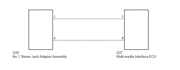
WIRING DIAGRAM
0.501,2.02 0.787,2.162
0.286,0.142
10
G26
0.501,2.174 2.750,2.316
2.248,0.142
10
No.1 Stereo Jack Adapter Assembly
2.131,0.587 2.239,0.736
0.107,0.149
10
1
2.131,1.442 2.239,1.591
0.107,0.149
10
4
4.839,1.442 4.946,1.591
0.107,0.149
10
4
4.839,0.587 4.946,0.736
0.107,0.149
10
1
4.634,2.02 4.920,2.162
0.286,0.142
10
G27
4.634,2.174 6.286,2.316
1.651,0.142
10
Muiti-media Interface ECU
PROCEDURE
1.REPLACE USB DEVICE OR "iPod"
a.
Disconnect the USB device or "iPod" from the stereo jack adapter.
b.
Turn the ignition switch off.
- HINT:
-
When this malfunction occurs, it is necessary to turn off the ignition switch to make it possible for the vehicle to recognize a new device when it is connected.
c.
Turn the ignition switch to ACC.
d.
Connect a known good USB device or "iPod" to the stereo jack adapter.
- OK:
USB device or "iPod" charges.
OK
USB DEVICE OR "iPod" WAS DEFECTIVE
NG
2.CHECK MULTI-MEDIA INTERFACE ECU
2.CHECK MULTI-MEDIA INTERFACE ECU
a.
0.042,0 0.292,0.188
0.25,0.188
10
false
*a
1.594,0.417 1.927,0.604
0.333,0.188
10
false
G26
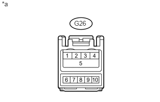
Disconnect the G26 No. 1 stereo jack adapter assembly connector.
b.
Measure the voltage according to the value(s) in the table below.
- Standard Voltage:
Tester Connection Condition Specified Condition G26-1 - G26-4 Always 5 V
| *a | Front view of wire harness connector
(to No. 1 Stereo Jack Adapter Assembly) |
OK
REPLACE NO. 1 STEREO JACK ADAPTER ASSEMBLY
NG
3.CHECK HARNESS AND CONNECTOR (MULTI-MEDIA INTERFACE ECU - STEREO JACK ADAPTER)
3.CHECK HARNESS AND CONNECTOR (MULTI-MEDIA INTERFACE ECU - STEREO JACK ADAPTER)
a.
Disconnect the G27 multi-media interface ECU connector.
b.
Disconnect the G26 No. 1 stereo jack adapter assembly connector.
c.
Measure the resistance according to the value(s) in the table below.
- Standard Resistance:
Tester Connection Condition Specified Condition G27-1 - G26-1 Always Below 1 Ω G27-4 - G26-4 Always Below 1 Ω G27-1 - Body ground Always 10 kΩ or higher G27-4 - Body ground Always 10 kΩ or higher
OK
PROCEED TO NEXT SUSPECTED AREA SHOWN IN PROBLEM SYMPTOMS TABLE
NG
REPAIR OR REPLACE HARNESS OR CONNECTOR