RM1440E
_57
Power Source / Network
_056154
NETWORKING
_0274053
CAN COMMUNICATION SYSTEM
U
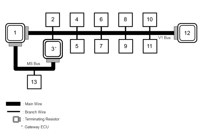
NETWORKING CAN COMMUNICATION SYSTEM SYSTEM DIAGRAM
5.646,1.26 6.188,1.438
0.542,0.177
10
false
V1 Bus
0.813,3.625 1.635,3.813
0.823,0.188
10
false
: Main Wire
0.813,3.917 1.719,4.094
0.906,0.177
10
false
: Branch Wire
0.813,4.167 2.208,4.344
1.396,0.177
10
false
: Terminating Resistor
0.75,4.448 1.844,4.667
1.094,0.219
10
false
*: Gateway ECU
0.958,2.188 1.573,2.365
0.615,0.177
10
false
MS Bus
1.958,1.646 2.073,1.823
0.115,0.177
10
false
*
| No. | ECU/Sensor Name |
|---|---|
| 1 | Combination meter assembly |
| 2 | Skid control ECU (master cylinder solenoid) |
| 3 | Main body ECU (multiplex network body ECU) |
| 4 | Airbag sensor assembly |
| 5 | Steering angle sensor (spiral cable sub-assembly) |
| 6 | DLC3 |
| 7 | Radio and display receiver assembly*1 |
| 8 | Yaw rate sensor assembly |
| 9 | Power steering ECU assembly |
| 10 | Four wheel drive control ECU*2 |
| 11 | Air conditioning amplifier assembly |
| 12 | ECM |
| 13 | Front power seat switch LH*3 |
*1: w/ Radio and Display Receiver Assembly
*2: for 4WD
*3: w/ Seat Position Memory
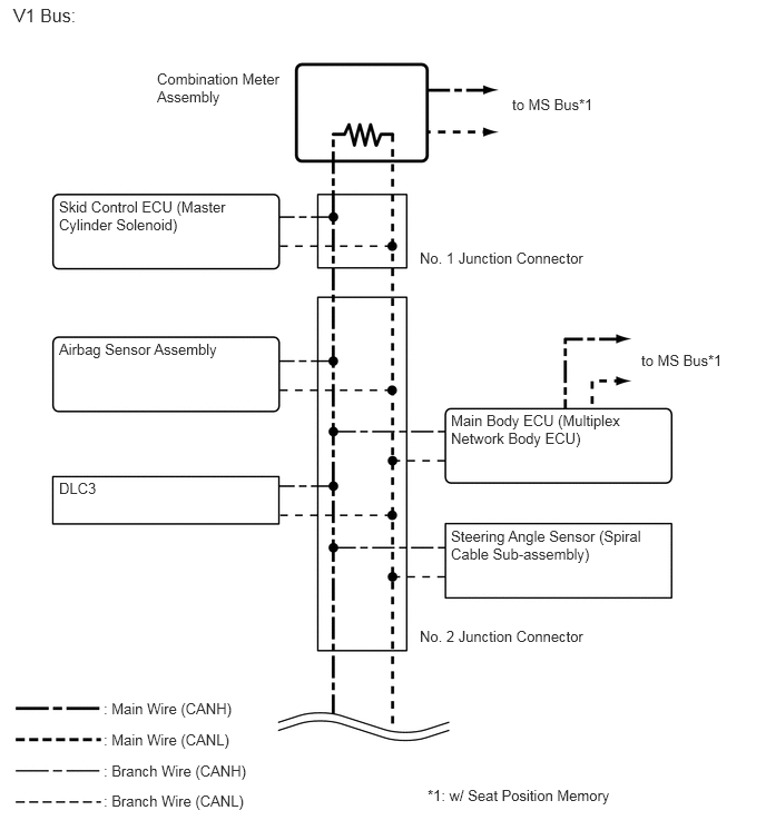
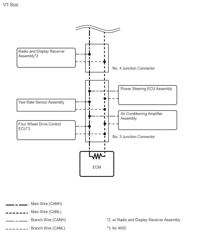
V1 BUS
6,3.292 6.885,3.479
0.885,0.188
10
false
to MS Bus*1
4.792,0.896 5.677,1.083
0.885,0.188
10
false
to MS Bus*1
4,7.365 6.302,7.573
2.302,0.208
10
false
*1: w/ Seat Position Memory
0.552,1.854 2.188,2.281
1.635,0.427
10
false
Skid Control ECU (Master Cylinder Solenoid)
0.552,3.188 2.188,3.396
1.635,0.208
10
false
Airbag Sensor Assembly
1.469,0.656 2.667,1.063
1.198,0.406
10
false
Combination Meter Assembly
0.552,4.49 0.958,4.708
0.406,0.219
10
false
DLC3
0.969,6.552 2.292,6.76
1.323,0.208
10
false
: Main Wire (CANH)
0.969,6.844 2.292,7.052
1.323,0.208
10
false
: Main Wire (CANL)
0.969,7.135 2.396,7.344
1.427,0.208
10
false
: Branch Wire (CANH)
0.969,7.417 2.396,7.625
1.427,0.208
10
false
: Branch Wire (CANL)
3.927,2.333 5.573,2.51
1.646,0.177
10
false
No. 1 Junction Connector
3.927,5.875 5.552,6.052
1.625,0.177
10
false
No. 2 Junction Connector
4.219,3.854 5.885,4.302
1.667,0.448
10
false
Main Body ECU (Multiplex Network Body ECU)
4.219,4.938 6.063,5.344
1.844,0.406
10
false
Steering Angle Sensor (Spiral Cable Sub-assembly)
0.125,0.042 0.74,0.26
0.615,0.219
12
false
V1 Bus:
3.354,5.969 3.771,6.167
0.417,0.198
10
false
ECM
0.667,3.615 2.417,3.854
1.75,0.24
10
false
Yaw Rate Sensor Assembly
0.667,4.406 2.271,4.792
1.604,0.385
10
false
Four Wheel Drive Control ECU*3
4.365,3.125 6.333,3.313
1.969,0.188
10
false
Power Steering ECU Assembly
4.073,2.385 5.729,2.573
1.656,0.188
10
false
No. 4 Junction Connector
4.073,4.865 5.698,5.042
1.625,0.177
10
false
No. 3 Junction Connector
4.365,4.031 5.969,4.427
1.604,0.396
10
false
Air Conditioning Amplifier Assembly
3.865,8.177 6.354,8.385
2.49,0.208
10
false
*3: for 4WD
3.865,7.875 6.813,8.083
2.948,0.208
10
false
*2: w/ Radio and Display Receiver Assembly
1.042,7.292 2.365,7.5
1.323,0.208
10
false
: Main Wire (CANH)
1.042,7.583 2.365,7.792
1.323,0.208
10
false
: Main Wire (CANL)
1.042,7.875 2.469,8.083
1.427,0.208
10
false
: Branch Wire (CANH)
1.042,8.177 2.469,8.385
1.427,0.208
10
false
: Branch Wire (CANL)
0.115,0.063 0.76,0.281
0.646,0.219
12
false
V1 Bus:
0.667,1.771 2.396,2.146
1.729,0.375
10
false
Radio and Display Receiver Assembly*2
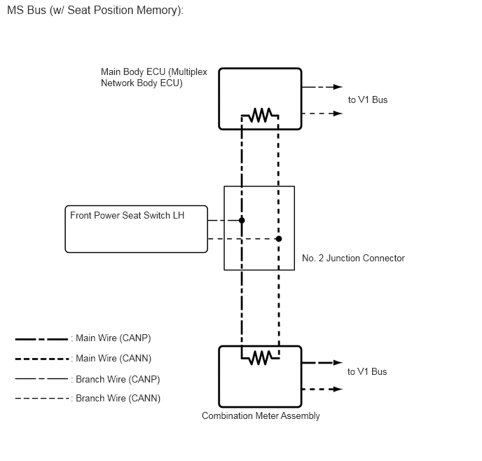
MS BUS
5.167,5.438 5.896,5.635
0.729,0.198
10
false
to V1 Bus
5.177,1.396 5.906,1.594
0.729,0.198
10
false
to V1 Bus
1.5,0.979 3.177,1.344
1.677,0.365
10
false
Main Body ECU (Multiplex Network Body ECU)
3,6.094 4.875,6.302
1.875,0.208
10
false
Combination Meter Assembly
0.104,0.042 2.74,0.271
2.635,0.229
12
false
MS Bus (w/ Seat Position Memory):
4.49,3.75 6.135,3.927
1.646,0.177
10
false
No. 2 Junction Connector
1.042,3.115 2.896,3.333
1.854,0.219
10
false
Front Power Seat Switch LH
1.052,4.938 2.375,5.146
1.323,0.208
10
false
: Main Wire (CANP)
1.052,5.24 2.375,5.448
1.323,0.208
10
false
: Main Wire (CANN)
1.052,5.552 2.479,5.76
1.427,0.208
10
false
: Branch Wire (CANP)
1.052,5.833 2.479,6.042
1.427,0.208
10
false
: Branch Wire (CANN)
- HINT:
- ·
The skid control ECU (master cylinder solenoid) stores steering angle sensor (spiral cable sub-assembly) and yaw rate sensor assembly DTCs and performs DTC communication by receiving information from the steering angle sensor (spiral cable sub-assembly) and yaw rate sensor assembly.
·The ECM uses the CAN communication system to perform DTC communication instead of the conventional communication line (SIL).