RM1440E
_58
Vehicle Interior
_056158
METER / GAUGE / DISPLAY
_0274083
METER / GAUGE SYSTEM
U
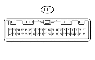
METER / GAUGE / DISPLAY METER / GAUGE SYSTEM TERMINALS OF ECU
COMBINATION METER ASSEMBLY
1.594,0.26 1.917,0.448
0.323,0.188
10
false
F14
a.
Measure the voltage and resistance according to the value(s) in the table below.
| Terminal No. (Symbol) | Wiring Color | Terminal Description | Condition | Specified Condition |
|---|---|---|---|---|
| 1 (CANH) - Body ground | L - Body ground | CAN communication signal | Ignition switch off | 200 Ω or higher |
| 2 (CANL) - Body ground | W - Body ground | CAN communication signal | Ignition switch off | 200 Ω or higher |
| 3 (MSSL) - Body ground*1 | P - Body ground | Steering pad switch assembly (DISP switch) signal | Ignition switch to ON, DISP switch not pressed | 4 to 5 V |
| Ignition switch to ON, DISP switch pressed | Below 1 V | |||
| 4 (TX+) - Body ground | B - Body ground | UART (Accessory meter output) | Ignition switch ON | Pulse generation |
| 5 (RX+) - Body ground | P - Body ground | UART (Accessory meter reset) | Ignition switch ON | Pulse generation |
| 7 (RR) - Body ground*2 | Y - Body ground | Ultrasonic sensor (for rear corner RH) | Clearance warning indication for rear corner RH is displayed | Below 3 V |
| 8 (S) - Body ground | V - Body ground | Oil pressure switch signal | Ignition switch ON, oil pressure warning light off | 11 to 14 V |
| Ignition switch ON, oil pressure warning light on | Below 1 V | |||
| 10 (IL2-) - Body ground | GR - Body ground | Illumination signal | Light control switch off | Below 1 V |
| Light control switch in tail or head position | Pulse generation | |||
| 11 (ILL-) - Body ground | GR - Body ground | Illumination signal | Light control switch off | Below 1 V |
| Light control switch in tail or head position | Pulse generation | |||
| 12 (RL) - Body ground*2 | GR - Body ground | Ultrasonic sensor (for rear corner LH) | Clearance warning indication for rear corner LH is displayed | Below 3 V |
| 13 (MGND) - Body ground | W-B - Body ground | Ground (Signal ground) | Always | Below 1 V |
| 15 (B) - Body ground | L - Body ground | Battery | Always | 11 to 14 V |
| 17 (+IG) - Body ground | R - Body ground | Ignition switch signal | Ignition switch off | Below 1 V |
| Ignition switch ON | 11 to 14 V | |||
| 18 (BK) - Body ground*2 | SB - Body ground | Ultrasonic sensor (for rear corner LH and RH) | Clearance warning indication for back right and left sensor is displayed | Below 3 V |
| 19 (E3) - Body ground | B - Body ground | Ground (Fuel ground) | Always | Below 1 V |
| 20 (E1) - Body ground | W-B - Body ground | Ground | Always | Below 1 V |
| 23 (MSCH) - Body ground*3 | LG - Body ground | CAN communication signal | Ignition switch off | 200 Ω or higher |
| 24 (MSCL) - Body ground*3 | W - Body ground | CAN communication signal | Ignition switch off | 200 Ω or higher |
| 25 (B) - Body ground | SB - Body ground | Turn indicator light signal | Ignition switch ON, turn RH indicator light off | Below 1 V |
| Ignition switch ON, turn RH indicator light blinking | 11 to 14 V | |||
| 26 (CHG-) - Body ground | P - Body ground | Charge warning light signal | Ignition switch ON, charge warning light off | 11 to 14 V |
| Ignition switch ON, charge warning light on | Below 1 V | |||
| 28 (+S) - Body ground | SB - Body ground | Speed signal for other systems (Output) | Driving at approx. 20 km/h (12 mph) | Pulse generation (See waveform 1) |
| 29 (SI) - Body ground | G - Body ground | Speed signal for other systems (Input) | Driving at approx. 20 km/h (12 mph) | Pulse generation (See waveform 1) |
| 30 (CHK) - Body ground | L - Body ground | MIL (Check engine warning light) signal | Ignition switch ON, MIL (Check engine warning light) off | 11 to 14 V |
| Ignition switch ON, MIL (Check engine warning light) on | Below 1 V | |||
| 31 (OP) - Body ground*2 | LG - Body ground | Clearance warning ECU signal | Clearance warning indication is displayed | Below 3 V |
| 32 (FL) - Body ground*2 | P - Body ground | Ultrasonic sensor (for front corner LH) | Clearance warning indication for front corner LH is displayed | Below 3 V |
| 33 (B) - Body ground | Y - Body ground | Turn indicator light signal | Ignition switch ON, turn LH indicator light off | Below 1 V |
| Ignition switch ON, turn LH indicator light blinking | 11 to 14 V | |||
| 34 (PBKL) - Body ground | P - Body ground | Passenger seat belt buckle switch signal | Front passenger seat occupied, seat belt fastened | 11 to 14 V |
| Front passenger seat occupied, seat belt unfastened | Below 1 V | |||
| 35 (FR) - Body ground*2 | B - Body ground | Ultrasonic sensor (for front corner RH) | Clearance warning indication for front corner RH is displayed | Below 3 V |
| 36 (TC) - Body ground*1 | W - Body ground | TAIL cancel switch signal | TAIL cancel switch off | 1 MΩ or higher |
| TAIL cancel switch on | Below 1 Ω | |||
| 37 (RHIG) - Body ground | B - Body ground | Power source for light control rheostat | Ignition switch ON | 4.6 to 5.4 V |
| 38 (TR) - Body ground | GR - Body ground | Light control rheostat signal | Light control rheostat dial fully turned downward | Below 1 Ω |
| Light control rheostat dial fully turned upward | 8 to 12 kΩ | |||
| 39 (E2) - Body ground | LG - Body ground | Light control rheostat switch ground | Always | Below 1 Ω |
| 40 (L) - Body ground | W - Body ground | Fuel level signal | Ignition switch ON, fuel level warning light off | Below 4 V |
| Ignition switch ON, fuel level warning light on | 4 to 9 V |
*1: for Optitron Meter
*2: w/ TOYOTA Parking Assist-sensor System
*3: w/ Seat Position Memory
b.
0.917,1.615 1.188,1.802
0.271,0.188
10
false
(A)
2.823,1.229 3.188,1.406
0.365,0.177
10
false
GND
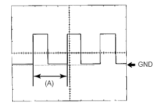
Using an oscilloscope, check waveform 1.
| Item | Condition |
|---|---|
| Tool setting | 5 V/DIV., 20 ms./DIV. |
| Vehicle condition | Driving at approx. 20 km/h (12 mph) |
- HINT:
-
When the system is functioning normally, one wheel revolution generates 4 pulses. As the vehicle speed increases, the width indicated by (A) in the illustration narrows.
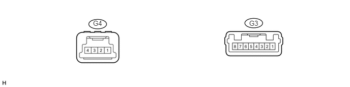
ACCESSORY METER ASSEMBLY
1.906,0.396 2.125,0.563
0.219,0.167
10
false
G4
5.104,0.396 5.323,0.563
0.219,0.167
10
false
G3
a.
Measure the voltage and resistance according to the value(s) in the table below.
| Terminal No. (Symbol) | Wiring Color | Terminal Description | Condition | Specified Condition |
|---|---|---|---|---|
| G3-1 (E) - Body ground | W-B - Body ground | Ground | Always | Below 1 Ω |
| G3-2 (DATA) - Body ground | B - Body ground | URAT (Accessory meter communication) signal | Ignition switch ON | Pulse generation |
| G3-3 (TH+) - Body ground | P - Body ground | URAT (Accessory meter communication) signal | Ignition switch ON | Pulse generation |
| G3-5 (IG+) - Body ground | L - Body ground | Ignition switch signal | Ignition switch off | Below 1 V |
| Ignition switch ON | 11 to 14 V | |||
| G3-6 (ACC) - Body ground | P - Body ground | Ignition switch signal | Ignition switch off | Below 1 V |
| Ignition switch ACC | 11 to 14 V | |||
| G3-7 (B) - Body ground | L - Body ground | Battery | Always | 11 to 14 V |
| G4-1 (ILL+) - Body ground | G - Body ground | Illumination signal | Light control switch in tail or head position | 11 to 14 V |
| G4-4 (ILL-) - Body ground | GR - Body ground | Illumination signal | Light control switch off | Below 1 V |
| Ignition switch ON, light control switch in tail or head position | Pulse generation |