RM1440E
_58
Vehicle Interior
_056158
METER / GAUGE / DISPLAY
_0274087
LIGHT CONTROL RHEOSTAT
G
METER / GAUGE / DISPLAY LIGHT CONTROL RHEOSTAT INSPECTION
PROCEDURE

 84119
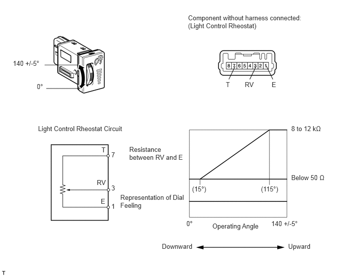
1.INSPECT LIGHT CONTROL RHEOSTAT (w/o TAIL Cancel Switch)
a.
Measure the resistance according to the value(s) in the table below.
0.271,1.245 0.906,1.401
0.635,0.156
10
140 +/-5°
0.776,1.743 0.959,1.899
0.184,0.156
10
0°
3.964,0.296 6.465,0.646
2.501,0.350
10
Component without harness connected: (Light Control Rheostat)
4.049,3.896 4.399,4.052
0.350,0.156
10
(15°)
5.501,3.896 5.903,4.052
0.401,0.156
10
(115°)
6.139,2.63 6.850,2.791
0.711,0.161
10
8 to 12 kΩ
6.139,3.657 6.975,3.818
0.836,0.161
10
Below 50 Ω
2.725,3.062 3.909,3.392
1.184,0.330
10
Resistance between RV and E
2.536,4.078 3.949,4.394
1.413,0.316
10
Representation of Dial Feeling
3.929,4.62 4.092,4.776
0.163,0.156
10
0°
5.718,4.62 6.353,4.776
0.635,0.156
10
140 +/-5°
4.476,4.676 5.519,4.860
1.042,0.184
10
Operating Angle
3.412,5.101 4.102,5.285
0.691,0.184
10
Downward
6.074,5.101 6.584,5.285
0.510,0.184
10
Upward
5.727,1.698 5.844,1.853
0.118,0.156
10
E
5.159,1.698 5.381,1.853
0.222,0.156
10
RV
4.76,1.698 4.878,1.853
0.118,0.156
10
T
5.618,1.396 5.751,1.67
false
5.398,1.396 5.264,1.67
false
4.956,1.396 4.823,1.67
false
0.803,2.621 2.658,2.800
1.855,0.179
10
Light Control Rheostat Circuit
2.125,4.154 2.262,4.319
0.137,0.165
10
E
2.041,3.764 2.262,3.929
0.221,0.165
10
RV
2.139,3.078 2.262,3.243
0.123,0.165
10
T
2.347,4.258 2.456,4.428
0.110,0.170
10
1
2.347,3.877 2.456,4.047
0.110,0.170
10
3
2.347,3.177 2.456,3.347
0.110,0.170
10
7
- Standard resistance:
Tester Connection Switch Condition Specified Condition 7 (T) - 1 (E) Always 8 to 12 kΩ 3 (RV) - 1 (E) Light control rheostat fully turned upward → fully turned downward 8 to 12 kΩ → Below 50 Ω
If the result is not as specified, replace the rheostat.
84119
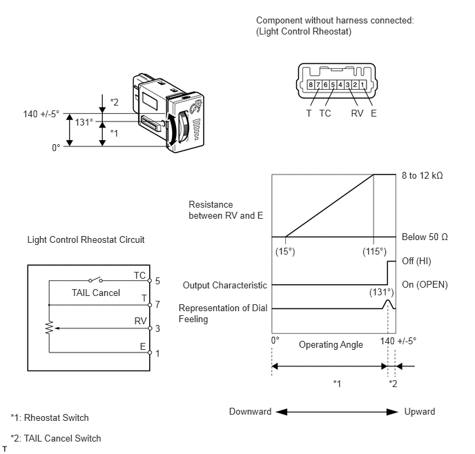
2.INSPECT LIGHT CONTROL RHEOSTAT (w/ TAIL Cancel Switch)
a.
Measure the resistance according to the value(s) in the table below.
0.343,1.631 0.939,1.782
0.596,0.151
10
140 +/-5°
0.782,2.147 0.943,2.298
0.161,0.151
10
0°
1.126,1.762 1.439,1.913
0.313,0.151
10
131°
1.661,1.463 1.817,1.614
0.156,0.151
10
*2
1.661,1.932 1.817,2.083
0.156,0.151
10
*1
0.411,3.536 2.266,3.715
1.855,0.179
10
Light Control Rheostat Circuit
3.863,0.219 6.353,0.569
2.489,0.350
10
Component without harness connected: (Light Control Rheostat)
6.062,2.56 6.739,2.730
0.677,0.170
10
8 to 12 kΩ
6.062,3.492 6.814,3.662
0.752,0.170
10
Below 50 Ω
5.73,5.059 6.326,5.210
0.596,0.151
10
140 +/-5°
4.087,5.049 4.247,5.200
0.161,0.151
10
0°
5.571,4.326 5.991,4.477
0.420,0.151
10
(131°)
4.154,3.709 4.495,3.860
0.341,0.151
10
(15°)
5.469,3.709 5.884,3.860
0.415,0.151
10
(115°)
2.755,4.214 4.096,4.391
1.341,0.178
10
Output Characteristic
2.695,4.563 4.092,4.900
1.398,0.338
10
Representation of Dial Feeling
4.507,5.113 5.547,5.301
1.040,0.188
10
Operating Angle
5.866,5.707 6.022,5.858
0.156,0.151
10
*2
5.025,5.707 5.181,5.858
0.156,0.151
10
*1
3.456,6.13 4.162,6.318
0.706,0.188
10
Downward
6.099,6.13 6.603,6.318
0.504,0.188
10
Upward
2.846,2.997 4.042,3.340
1.195,0.343
10
Resistance between RV and E
0.159,6.527 1.627,6.678
1.468,0.151
10
*2: TAIL Cancel Switch
0.159,6.217 1.408,6.368
1.250,0.151
10
*1: Rheostat Switch
6.062,3.856 6.553,4.026
0.492,0.170
10
Off (HI)
6.062,4.204 6.824,4.373
0.762,0.170
10
On (OPEN)
5.595,1.63 5.732,1.795
0.137,0.165
10
E
5.262,1.324 5.395,1.597
false
5.296,1.63 5.517,1.795
0.221,0.165
10
RV
4.815,1.63 5.036,1.795
0.221,0.165
10
TC
4.619,1.63 4.742,1.795
0.123,0.165
10
T
5.486,1.324 5.619,1.597
false
5.04,1.324 4.907,1.597
false
4.816,1.324 4.683,1.597
false
2.111,5.146 2.248,5.312
0.137,0.165
10
E
2.027,4.763 2.248,4.929
0.221,0.165
10
RV
2.018,4.068 2.238,4.233
0.221,0.165
10
TC
2.134,4.413 2.258,4.578
0.123,0.165
10
T
2.34,5.25 2.449,5.420
0.110,0.170
10
1
2.34,4.877 2.449,5.047
0.110,0.170
10
3
2.34,4.158 2.449,4.327
0.110,0.170
10
5
2.34,4.512 2.449,4.682
0.110,0.170
10
7
1.081,4.334 1.872,4.485
0.791,0.151
10
TAIL Cancel
- Standard resistance:
Tester Connection Switch Condition Specified Condition 7 (T) - 1 (E) Always 8 to 12 kΩ 5 (TC) - 7 (T) TAIL cancel switch off → on Below 50 Ω → 8 to 12 kΩ 3 (RV) - 1 (E) Light control rheostat fully turned upward → fully turned downward 8 to 12 kΩ → Below 50 Ω
If the result is not as specified, replace the rheostat.