RM1440E
_58
Vehicle Interior
_056163
HEATING / AIR CONDITIONING
_0274143
AIR CONDITIONING PRESSURE SENSOR
G
HEATING / AIR CONDITIONING AIR CONDITIONING PRESSURE SENSOR ON-VEHICLE INSPECTION
PROCEDURE

 88645H
1.INSPECT NO. 1 PRESSURE SWITCH
a.
1.615,0.969 1.229,0.583
true
1.823,0.969 2.208,0.583
true
1.125,0.396 1.229,0.552
0.104,0.156
10
false
1
2.219,0.406 2.323,0.552
0.104,0.146
10
false
2
0.5,2.677 1.042,2.844
0.542,0.167
10
false
196 kPa
2.385,2.667 3.052,2.823
0.667,0.156
10
false
3140 kPa
0.125,0.188 0.333,0.375
0.208,0.188
10
false
*a
0.823,1.833 1.031,2.021
0.208,0.188
10
false
*b
1.656,1.833 1.833,2.01
0.177,0.177
10
false
*c
2.552,1.833 2.729,2.031
0.177,0.198
10
false
*d
0.698,3.063 0.906,3.219
0.208,0.156
10
false
*e
2.708,3.063 2.875,3.219
0.167,0.156
10
false
*e
0.021,2.833 1.26,3.052
1.24,0.219
10
false
(2.0 kgf*cm, 28 psi)
1.729,2.844 3.104,3.052
1.375,0.208
10
false
(32.0 kgf*cm, 455 psi)
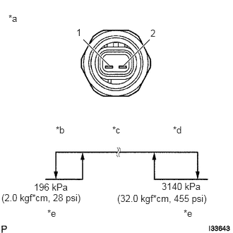
Set on the manifold gauge set.
| *a | Component without harness connected
(No. 1 Pressure Switch) |
| *b | Low Pressure Side |
| *c | High Pressure Side |
| *d | High Pressure Side |
| *e | Off (10kΩ or higher) |
b.
Connect the positive (+) lead from the ohmmeter to terminal 1 and the negative (-) lead to terminal 2.
c.
Check the continuity between terminals when refrigerant pressure is charged, as shown in the illustration.
If operation is not as specified, replace the pressure switch.