INTERIOR PANELS / TRIM ROOF HEADLINING REASSEMBLY
PROCEDURE

 82171
1.INSTALL NO. 1 ROOF WIRE
Apply butyl tape to the roof headlining so that the tape is aligned with the wire harness marking as shown in the illustration.
- HINT:
-
Use butyl tape that has a width of 10 mm (0.394 in.).
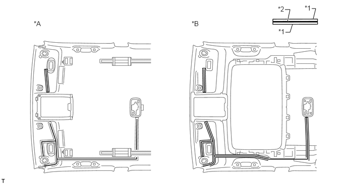
| *A | w/o Sliding Roof | *B | w/ Sliding Roof |
| *1 | Wire Harness Marking | *2 | Butyl Tape |
Align the marking tape on the No. 1 roof wire with the roof tongue of the roof headlining as shown in the part of the illustration labeled A and attach the wire to the hook.
Align the marking tape on the No. 1 roof wire with the V mark on the roof headlining as shown in the part of the illustration labeled B and attach the wire to the roof headlining to install it.
- HINT:
- ·
For the area in the illustration labeled E, attach the No. 1 roof wire so that its marked surface contacts the roof headlining.
·Be sure to securely attach the roof wire so that it is not twisted.
Attach each clamp.
Turn the visor connectors approximately 90° clockwise to install them to the roof headlining.
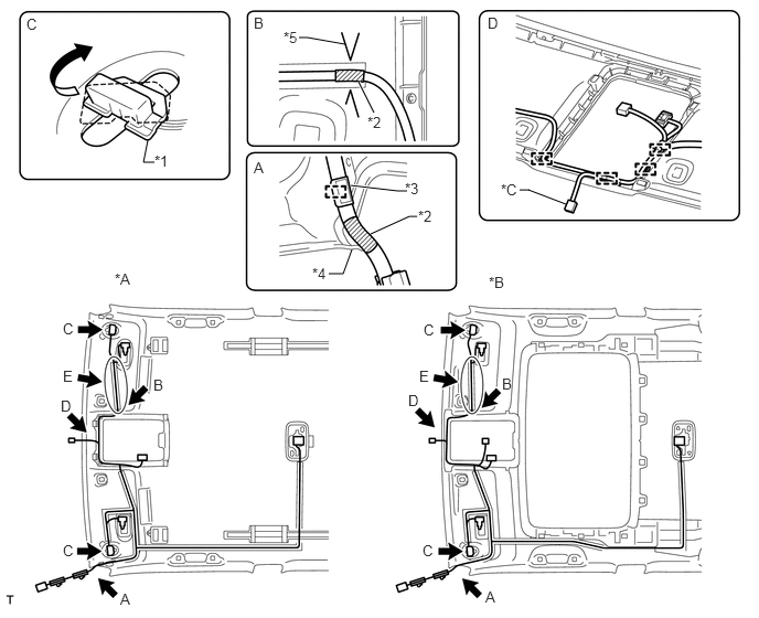
| *A | w/o Sliding Roof | *B | w/ Sliding Roof |
| *C | w/ EC Mirror | - | - |
| *1 | Visor Connector | *2 | Marking Tape |
| *3 | Hook | *4 | Roof Tongue |
| *5 | V Mark | - | - |
81340
2.INSTALL VANITY LIGHT ASSEMBLY
- HINT:
-
Use the same procedure for the other vanity light.
Attach the 3 claws to install the vanity light.
63344
3.INSTALL NO. 4 ROOF SILENCER PAD
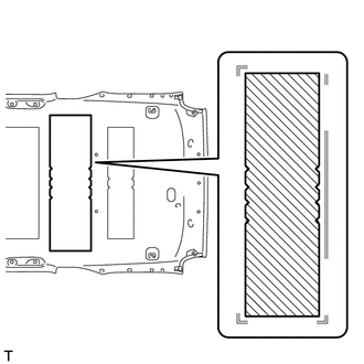
w/o Sliding Roof:
Align the No. 4 roof silencer pad with the markings on the roof headlining and install the No. 4 roof silencer pad to the position shown in the illustration using hot-melt glue or double-sided tape.
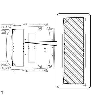
w/ Sliding Roof:
Align the No. 4 roof silencer pad with the markings on the roof headlining and install the No. 4 roof silencer pad to the position shown in the illustration using hot-melt glue or double-sided tape.
63343
4.INSTALL NO. 3 ROOF SILENCER PAD (w/o Sliding Roof)
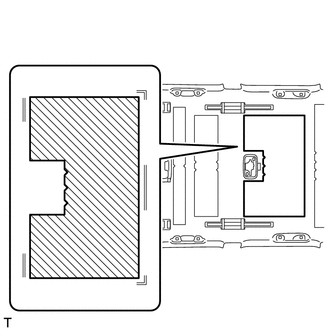
Align the No. 3 roof silencer pad with the markings on the roof headlining and install the No. 3 roof silencer pad to the position shown in the illustration using hot-melt glue or double-sided tape.
63342
5.INSTALL NO. 2 ROOF SILENCER PAD
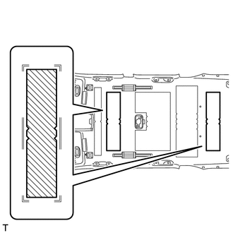
w/o Sliding Roof:
Align the 2 No. 2 roof silencer pads with the markings on the roof headlining and install the 2 No. 2 roof silencer pads to the position shown in the illustration using hot-melt glue or double-sided tape.
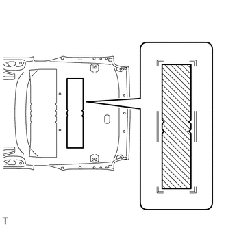
w/ Sliding Roof:
Align the No. 2 roof silencer pad with the markings on the roof headlining and install the No. 2 roof silencer pad to the position shown in the illustration using hot-melt glue or double-sided tape.
63341
6.INSTALL NO. 1 ROOF SILENCER PAD (w/o Sliding Roof)
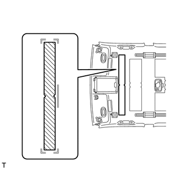
Align the No. 1 roof silencer pad with the markings on the roof headlining and install the No. 1 roof silencer pad to the position shown in the illustration using hot-melt glue or double-sided tape.