RM1440E
_59
Vehicle Exterior
_056171
LIGHTING (EXT)
_0274208
HAZARD WARNING SWITCH
G
LIGHTING (EXT) HAZARD WARNING SWITCH INSPECTION
PROCEDURE

 84330
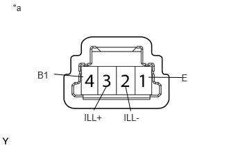
1.INSPECT HAZARD WARNING SIGNAL SWITCH ASSEMBLY
a.
0.192,0.033 0.348,0.215
0.156,0.181
10
*a
0.562,1.037 0.757,1.219
0.194,0.181
10
B1
1.262,1.676 1.553,1.857
0.291,0.181
10
ILL+
1.856,1.673 2.113,1.854
0.256,0.181
10
ILL-
2.724,1.083 2.880,1.264
0.156,0.181
10
E
0.811,1.11 1.249,1.152
false
1.594,1.301 1.407,1.65
false
1.887,1.305 1.962,1.664
false
2.227,1.156 2.735,1.161
false
Measure the resistance according to the value(s) in the table below.
- Standard Resistance:
Tester Connection Switch Condition Specified Condition 4 (B1) - 1 (E) Hazard warning signal switch off 10 kΩ or higher Hazard warning signal switch on Below 1 Ω
b.
Apply battery voltage to the connector and check the LED illumination condition.
- OK:
Measurement Condition Specified Condition Battery positive (+) → Terminal 3 (ILL+)
Battery negative (-) → Terminal 2 (ILL-)LED illuminates
If the result is not as specified, there may be a malfunction in the hazard warning signal switch.
| *a | Component without harness connected
(Hazard Warning Signal Switch Assembly) |