RM1440E
_59
Vehicle Exterior
_056171
LIGHTING (EXT)
_0274209
STOP LIGHT SWITCH
A
LIGHTING (EXT) STOP LIGHT SWITCH INSTALLATION
PROCEDURE

 84345
1.INSTALL STOP LIGHT SWITCH MOUNTING ADJUSTER
a.
Install the stop light switch mounting adjuster to the pedal support.
84340
2.INSTALL STOP LIGHT SWITCH ASSEMBLY
a.
2.24,1.344 2.052,1.719
false
1.208,1.198 1.448,1.323
false
0.583,1.198 0.521,1.365
false
1.365,1.333 1.542,1.531
0.177,0.198
10
false
*2
0.427,1.375 0.615,1.552
0.188,0.177
10
false
*1
1.969,1.74 2.167,1.927
0.198,0.188
10
false
*3
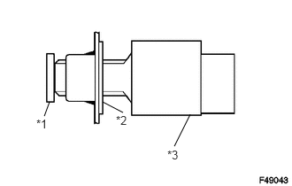
Install the stop light switch to the adjuster so that the switch body slightly touches the brake pedal.
| *1 | Brake Pedal |
| *2 | Adjuster |
| *3 | Stop Light Switch |
- NOTICE:
-
Do not depress the brake pedal.
b.
1.854,1.25 1.938,1.365
false
0.573,0.688 0.521,0.208
false
0.323,0.073 0.49,0.281
0.167,0.208
10
false
*1
1.896,1.375 2.083,1.583
0.188,0.208
10
false
*3
0.458,1.719 0.615,1.917
0.156,0.198
10
false
*2
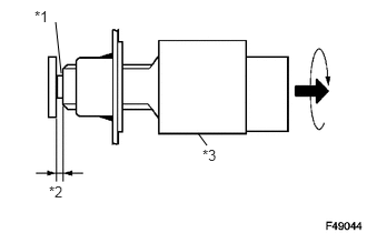
Rotate the stop light switch counterclockwise so that the clearance is between 1.5 and 2.5 mm (0.0590 to 0.0984 in.) as shown in the illustration.
- Torque:
- 1.5 N*m (15 kgf*cm, 13 in.*lbf)
| *1 | Shaft |
| *2 | 1.5 to 2.5 mm (0.0590 to 0.0984 in.) |
| *3 | Stop Light Switch |
- NOTICE:
-
Do not depress the brake pedal.
c.
Check the stop light switch clearance.
- Stop light switch clearance:
1.5 to 2.5 mm (0.0590 to 0.0984 in.)
d.
Connect the connector to the stop light switch.