
POWER WINDOW CONTROL SYSTEM > TERMINALS OF ECU |
| CHECK MULTIPLEX NETWORK MASTER SWITCH ASSEMBLY |
Disconnect the h1 multiplex network master switch connector.
Measure the voltage and resistance according to the value(s) in the table below.
| Terminal No. (Symbol) | Wiring Color | Terminal Description | Condition | Specified Condition |
| h1-11 (B) - h1-12 (GND) | G - W-B | Power supply | Always | 11 to 14 V |
| h1-12 (GND) - Body ground | W-B - Body ground | Ground | Always | Below 1 Ω |
Reconnect the h1 multiplex network master switch connector.
Measure the voltage according to the value(s) in the table below.
| Terminal No. (Symbol) | Wiring Color | Terminal Description | Condition | Specified Condition |
| h1-15 (DOWN) - h1-12 (GND) | B - W-B | Power window motor down input | Ignition switch ON, driver side power window regulator switch off | 11 to 14 V |
| h1-15 (DOWN) - h1-12 (GND) | B - W-B | Power window motor down input | Ignition switch ON, driver side power window switch down (Manual operation) | Below 1 V |
| h1-18 (LED) - h1-12 (GND) | V - W-B | LED illumination signal | Ignition switch ON | 11 to 14 V |
| h1-18 (LED) - h1-12 (GND) | V - W-B | LED illumination signal | Approximately 43 seconds after ignition switch turned off | Below 1 V |
| h1-20 (UP) - h1-12 (GND) | L - W-B | Power window motor up input | Ignition switch ON, driver side power window switch off | 11 to 14 V |
| h1-20 (UP) - h1-12 (GND) | L - W-B | Power window motor up input | Ignition switch ON, driver side power window switch up (Manual operation) | Below 1 V |
| CHECK POWER WINDOW REGULATOR SWITCH ASSEMBLY |

Disconnect the g1 power window regulator switch connector.
Measure the resistance according to the value(s) in the table below.
| Terminal No. (Symbol) | Wiring Color | Terminal Description | Condition | Specified Condition |
| g1-1 (GND) - Body ground | W-B - Body ground | Ground | Always | Below 1 Ω |
Reconnect the g1 power window regulator switch connector.
Measure the voltage according to the value(s) in the table below.
| Terminal No. (Symbol) | Wiring Color | Terminal Description | Condition | Specified Condition |
| g1-6 (UP) - g1-1 (GND) | L - W-B | Power window motor up input | Ignition switch ON, power window regulator switch off | 11 to 14 V |
| g1-6 (UP) - g1-1 (GND) | L - W-B | Power window motor up input | Ignition switch ON, power window regulator switch up | Below 1 V |
| g1-8 (AUTO) - g1-1 (GND) | P - W-B | Power window motor auto up or down input | Ignition switch ON, door glass fully open | 11 to 14 V |
| g1-8 (AUTO) - g1-1 (GND) | P - W-B | Power window motor auto up or down input | Ignition switch ON, power window auto up or down function operating | Below 1 V |
| g1-8 (AUTO) - g1-1 (GND) | P - W-B | Power window motor auto up or down input | Ignition switch ON, door glass fully closed | 11 to 14 V |
| g1-4 (LED) - g1-1 (GND) | V - W-B | LED illumination signal | Ignition switch ON | 11 to 14 V |
| g1-4 (LED) - g1-1 (GND) | V - W-B | LED illumination signal | Approximately 43 seconds after the ignition switch is turned off | Below 1 V |
| g1-7 (DOWN) - g1-1 (GND) | B - W-B | Power window motor down input | Ignition switch ON, power window regulator switch off | 11 to 14 V |
| g1-7 (DOWN) - g1-1 (GND) | B - W-B | Power window motor down input | Ignition switch ON, power window regulator switch down | Below 1 V |
| CHECK REAR POWER WINDOW REGULATOR SWITCH ASSEMBLY LH |

Disconnect the j1 rear power window regulator switch connector.
Measure the resistance according to the value(s) in the table below.
| Terminal No. (Symbol) | Wiring Color | Terminal Description | Condition | Specified Condition |
| j1-1 (GND) - Body ground | W-B - Body ground | Ground | Always | Below 1 Ω |
Reconnect the j1 rear power window regulator switch connector.
Measure the voltage according to the value(s) in the table below.
| Terminal No. (Symbol) | Wiring Color | Terminal Description | Condition | Specified Condition |
| j1-6 (UP) - j1-1 (GND) | L - W-B | Power window motor up input | Ignition switch ON, power window regulator switch off | 11 to 14 V |
| j1-6 (UP) - j1-1 (GND) | L - W-B | Power window motor up input | Ignition switch ON, power window regulator switch up | Below 1 V |
| j1-8 (AUTO) - j1-1 (GND) | P - W-B | Power window motor auto up or down input | Ignition switch ON, door glass fully open | 11 to 14 V |
| j1-8 (AUTO) - j1-1 (GND) | P - W-B | Power window motor auto up or down input | Ignition switch ON, power window auto up or down function operating | Below 1 V |
| j1-8 (AUTO) - j1-1 (GND) | P - W-B | Power window motor auto up or down input | Ignition switch ON, door glass fully closed | 11 to 14 V |
| j1-4 (LED) - j1-1 (GND) | V - W-B | LED illumination signal | Ignition switch ON | 11 to 14 V |
| j1-4 (LED) - j1-1 (GND) | V - W-B | LED illumination signal | Approximately 43 seconds after the ignition switch is turned off | Below 1 V |
| j1-7 (DOWN) - j1-1 (GND) | B - W-B | Power window motor down input | Ignition switch ON, power window regulator switch off | 11 to 14 V |
| j1-7 (DOWN) - j1-1 (GND) | B - W-B | Power window motor down input | Ignition switch ON, power window regulator switch down | Below 1 V |
| CHECK REAR POWER WINDOW REGULATOR SWITCH ASSEMBLY RH |

Disconnect the i1 rear power window regulator switch connector.
Measure the resistance according to the value(s) in the table below.
| Terminal No. (Symbol) | Wiring Color | Terminal Description | Condition | Specified Condition |
| i1-1 (GND) - Body ground | W-B - Body ground | Ground | Always | Below 1 Ω |
Reconnect the i1 rear power window regulator switch connector.
Measure the voltage according to the value(s) in the table below.
| Terminal No. (Symbol) | Wiring Color | Terminal Description | Condition | Specified Condition |
| i1-6 (UP) - i1-1 (GND) | L - W-B | Power window motor up input | Ignition switch ON, power window regulator switch off | 11 to 14 V |
| i1-6 (UP) - i1-1 (GND) | L - W-B | Power window motor up input | Ignition switch ON, power window regulator switch up | Below 1 V |
| i1-8 (AUTO) - i1-1 (GND) | P - W-B | Power window motor auto up or down input | Ignition switch ON, door glass fully open | 11 to 14 V |
| i1-8 (AUTO) - i1-1 (GND) | P - W-B | Power window motor auto up or down input | Ignition switch ON, power window auto up or down function operating | Below 1 V |
| i1-8 (AUTO) - i1-1 (GND) | P - W-B | Power window motor auto up or down input | Ignition switch ON, door glass fully closed | 11 to 14 V |
| i1-4 (LED) - i1-1 (GND) | V - W-B | LED illumination signal | Ignition switch ON | 11 to 14 V |
| i1-4 (LED) - i1-1 (GND) | V - W-B | LED illumination signal | Approximately 43 seconds after the ignition switch is turned off | Below 1 V |
| i1-7 (DOWN) - i1-1 (GND) | B - W-B | Power window motor down input | Ignition switch ON, power window regulator switch off | 11 to 14 V |
| i1-7 (DOWN) - i1-1 (GND) | B - W-B | Power window motor down input | Ignition switch ON, power window regulator switch down | Below 1 V |
| CHECK BACK DOOR POWER WINDOW REGULATOR SWITCH ASSEMBLY |

Disconnect the f1 back door power window regulator switch connector.
Measure the resistance according to the value(s) in the table below.
| Terminal No. (Symbol) | Wiring Color | Terminal Description | Condition | Specified Condition |
| f1-1 (E) - Body ground | W-B - Body ground | Ground | Always | Below 1 Ω |
Reconnect the f1 rear power window regulator switch connector.
Measure the voltage according to the value(s) in the table below.
| Terminal No. (Symbol) | Wiring Color | Terminal Description | Condition | Specified Condition |
| f1-6 (UP) - f1-1 (E) | P - W-B | Power window motor up input | Ignition switch ON, power window regulator switch off | 11 to 14 V |
| f1-6 (UP) - f1-1 (E) | P - W-B | Power window motor up input | Ignition switch ON, power window regulator switch up | Below 1 V |
| f1-8 (AUTO) - f1-1 (E) | B - W-B | Power window motor auto up or down input | Ignition switch ON, door glass fully open | 11 to 14 V |
| f1-8 (AUTO) - f1-1 (E) | B - W-B | Power window motor auto up or down input | Ignition switch ON, power window auto up or down function operating | Below 1 V |
| f1-8 (AUTO) - f1-1 (E) | B - W-B | Power window motor auto up or down input | Ignition switch ON, door glass fully closed | 11 to 14 V |
| f1-4 (ILL+) - f1-1 (E) | V - W-B | LED illumination signal | Ignition switch ON | 11 to 14 V |
| f1-4 (ILL+) - f1-1 (E) | V - W-B | LED illumination signal | Approximately 43 seconds after the ignition switch is turned off | Below 1 V |
| f1-7 (DOWN) - f1-1 (E) | R - W-B | Power window motor down input | Ignition switch ON, power window regulator switch off | 11 to 14 V |
| f1-7 (DOWN) - f1-1 (E) | R - W-B | Power window motor down input | Ignition switch ON, power window regulator switch down | Below 1 V |
| CHECK FRONT POWER WINDOW REGULATOR MOTOR ASSEMBLY LH |

Disconnect the I2 power window regulator motor connector.
Measure the voltage and resistance according to the value(s) in the table below.
| Terminal No. (Symbol) | Wiring Color | Terminal Description | Condition | Specified Condition |
| I2-1 (GND) - Body ground | W-B - Body ground | Ground | Always | Below 1 Ω |
| I2-2 (B) - Body ground | R - Body ground | Battery power supply | Always | 11 to 14 V |
Reconnect the I2 power window regulator motor connector.
Measure the voltage according to the value(s) in the table below.
| Terminal No. (Symbol) | Wiring Color | Terminal Description | Condition | Specified Condition |
| I2-5 (LED) - I2-1 (GND) | V - W-B | LED illumination signal | Ignition switch ON | 11 to 14 V |
| I2-5 (LED) - I2-1 (GND) | V - W-B | LED illumination signal | Approximately 43 seconds after ignition switch turned off | Below 1 V |
| I2-7 (DOWN) - I2-1 (GND) | B - W-B | Power window motor down output | Ignition switch ON, power window regulator master switch off | 11 to 14 V |
| I2-7 (DOWN) - I2-1 (GND) | B - W-B | Power window motor down output | Ignition switch ON, power window regulator master switch down | Below 1 V |
| I2-7 (DOWN) - I2-1 (GND) | B - W-B | Power window motor down output | Ignition switch ON, door glass fully closed | 11 to 14 V |
| I2-7 (DOWN) - I2-1 (GND) | B - W-B | Power window motor down output | Ignition switch ON, power window auto down function operating | Below 1 V |
| I2-7 (DOWN) - I2-1 (GND) | B - W-B | Power window motor down output | Ignition switch ON, door glass fully open | 11 to 14 V |
| I2-10 (UP) - I2-1 (GND) | L - W-B | Power window motor up output | Ignition switch ON, power window regulator master switch off | 11 to 14 V |
| I2-10 (UP) - I2-1 (GND) | L - W-B | Power window motor up output | Ignition switch ON, power window regulator master switch up | Below 1 V |
| I2-10 (UP) - I2-1 (GND) | L - W-B | Power window motor up output | Ignition switch ON, door glass fully open | 11 to 14 V |
| I2-10 (UP) - I2-1 (GND) | L - W-B | Power window motor up output | Ignition switch ON, power window auto up function operating | Below 1 V |
| I2-10 (UP) - I2-1 (GND) | L - W-B | Power window motor up output | Ignition switch ON, door glass fully closed | 11 to 14 V |
| CHECK FRONT POWER WINDOW REGULATOR MOTOR ASSEMBLY RH |

Disconnect the H2 power window regulator motor connector.
Measure the voltage and resistance according to the value(s) in the table below.
| Terminal No. (Symbol) | Wiring Color | Terminal Description | Condition | Specified Condition |
| H2-1 (GND) - Body ground | W-B - Body ground | Ground | Always | Below 1 Ω |
| H2-2 (B) - Body ground | G - Body ground | Battery power supply | Always | 11 to 14 V |
Reconnect the H2 power window regulator motor connector.
Measure the voltage according to the value(s) in the table below.
| Terminal No. (Symbol) | Wiring Color | Terminal Description | Condition | Specified Condition |
| H2-5 (LED) - H2-1 (GND) | V - W-B | LED illumination signal | Ignition switch ON | 11 to 14 V |
| H2-5 (LED) - H2-1 (GND) | V - W-B | LED illumination signal | Approximately 43 seconds after ignition switch turned off | Below 1 V |
| H2-7 (DOWN) - H2-1 (GND) | B - W-B | Power window motor down output | Ignition switch ON, power window regulator switch off | 11 to 14 V |
| H2-7 (DOWN) - H2-1 (GND) | B - W-B | Power window motor down output | Ignition switch ON, power window regulator switch down | Below 1 V |
| H2-7 (DOWN) - H2-1 (GND) | B - W-B | Power window motor down output | Ignition switch ON, door glass fully closed | 11 to 14 V |
| H2-7 (DOWN) - H2-1 (GND) | B - W-B | Power window motor down output | Ignition switch ON, power window auto down function operating | Below 1 V |
| H2-7 (DOWN) - H2-1 (GND) | B - W-B | Power window motor down output | Ignition switch ON, door glass fully open | 11 to 14 V |
| H2-10 (UP) - H2-1 (GND) | L - W-B | Power window motor up output | Ignition switch ON, power window regulator switch off | 11 to 14 V |
| H2-10 (UP) - H2-1 (GND) | L - W-B | Power window motor up output | Ignition switch ON, power window regulator switch up | Below 1 V |
| H2-10 (UP) - H2-1 (GND) | L - W-B | Power window motor up output | Ignition switch ON, door glass fully open | 11 to 14 V |
| H2-10 (UP) - H2-1 (GND) | L - W-B | Power window motor up output | Ignition switch ON, power window auto up function operating | Below 1 V |
| H2-10 (UP) - H2-1 (GND) | L - W-B | Power window motor up output | Ignition switch ON, door glass fully closed | 11 to 14 V |
| CHECK REAR POWER WINDOW REGULATOR MOTOR ASSEMBLY LH |

Disconnect the K2 rear power window regulator motor connector.
Measure the voltage and resistance according to the value(s) in the table below.
| Terminal No. (Symbol) | Wiring Color | Terminal Description | Condition | Specified Condition |
| K2-1 (GND) - Body ground | W-B - Body ground | Ground | Always | Below 1 Ω |
| K2-2 (B) - Body ground | W - Body ground | Battery power supply | Always | 11 to 14 V |
Reconnect the K2 rear power window regulator motor connector.
Measure the voltage according to the value(s) in the table below.
| Terminal No. (Symbol) | Wiring Color | Terminal Description | Condition | Specified Condition |
| K2-5 (LED) - K2-1 (GND) | V - W-B | LED illumination signal | Ignition switch ON | 11 to 14 V |
| K2-5 (LED) - K2-1 (GND) | V - W-B | LED illumination signal | Approximately 43 seconds after ignition switch turned off | Below 1 V |
| K2-7 (DOWN) - K2-1 (GND) | B - W-B | Power window motor down input | Ignition switch ON, power window regulator switch off | 11 to 14 V |
| K2-7 (DOWN) - K2-1 (GND) | B - W-B | Power window motor down input | Ignition switch ON, power window regulator switch down | Below 1 V |
| K2-7 (DOWN) - K2-1 (GND) | B - W-B | Power window motor down input | Ignition switch ON, door glass fully closed | 11 to 14 V |
| K2-7 (DOWN) - K2-1 (GND) | B - W-B | Power window motor down input | Ignition switch ON, power window auto down function operating | Below 1 V |
| K2-7 (DOWN) - K2-1 (GND) | B - W-B | Power window motor down input | Ignition switch ON, door glass fully open | 11 to 14 V |
| K2-10 (UP) - K2-1 (GND) | L - W-B | Power window motor up output | Ignition switch ON, power window regulator switch off | 11 to 14 V |
| K2-10 (UP) - K2-1 (GND) | L - W-B | Power window motor up output | Ignition switch ON, power window regulator switch up | Below 1 V |
| K2-10 (UP) - K2-1 (GND) | L - W-B | Power window motor up output | Ignition switch ON, door glass fully open | 11 to 14 V |
| K2-10 (UP) - K2-1 (GND) | L - W-B | Power window motor up output | Ignition switch ON, power window auto up function operating | Below 1 V |
| K2-10 (UP) - K2-1 (GND) | L - W-B | Power window motor up output | Ignition switch ON, door glass fully closed | 11 to 14 V |
| CHECK REAR POWER WINDOW REGULATOR MOTOR ASSEMBLY RH |

Disconnect the J2 rear window regulator motor connector.
Measure the voltage and resistance according to the value(s) in the table below.
| Terminal No. (Symbol) | Wiring Color | Terminal Description | Condition | Specified Condition |
| J2-1 (GND) - Body ground | W-B - Body ground | Ground | Always | Below 1 Ω |
| J2-2 (B) - Body ground | W - Body ground | Battery power supply | Always | 11 to 14 V |
Reconnect the J2 rear power window regulator motor connector.
Measure the voltage according to the value(s) in the table below.
| Terminal No. (Symbol) | Wiring Color | Terminal Description | Condition | Specified Condition |
| J2-5 (LED) - J2-1 (GND) | V - W-B | LED illumination signal | Ignition switch ON | 11 to 14 V |
| J2-5 (LED) - J2-1 (GND) | V - W-B | LED illumination signal | Approximately 43 seconds after ignition switch turned off | Below 1 V |
| J2-7 (DOWN) - J2-1 (GND) | B - W-B | Power window motor down output | Ignition switch ON, power window regulator switch off | 11 to 14 V |
| J2-7 (DOWN) - J2-1 (GND) | B - W-B | Power window motor down output | Ignition switch ON, power window regulator switch down | Below 1 V |
| J2-7 (DOWN) - J2-1 (GND) | B - W-B | Power window motor down output | Ignition switch ON, door glass fully closed | 11 to 14 V |
| J2-7 (DOWN) - J2-1 (GND) | B - W-B | Power window motor down output | Ignition switch ON, power window auto down function operating | Below 1 V |
| J2-7 (DOWN) - J2-1 (GND) | B - W-B | Power window motor down output | Ignition switch ON, door glass fully open | 11 to 14 V |
| J2-10 (UP) - J2-1 (GND) | L - W-B | Power window motor up output | Ignition switch ON, power window regulator switch off | 11 to 14 V |
| J2-10 (UP) - J2-1 (GND) | L - W-B | Power window motor up output | Ignition switch ON, power window regulator switch up | Below 1 V |
| J2-10 (UP) - J2-1 (GND) | L - W-B | Power window motor up output | Ignition switch ON, door glass fully open | 11 to 14 V |
| J2-10 (UP) - J2-1 (GND) | L - W-B | Power window motor up output | Ignition switch ON, power window auto up function operating | Below 1 V |
| J2-10 (UP) - J2-1 (GND) | L - W-B | Power window motor up output | Ignition switch ON, door glass fully closed | 11 to 14 V |
| CHECK BACK DOOR POWER WINDOW REGULATOR MOTOR ASSEMBLY |

Disconnect the W9 back door power window regulator motor connector.
Measure the voltage and resistance according to the value(s) in the table below.
| Terminal No. (Symbol) | Wiring Color | Terminal Description | Condition | Specified Condition |
| W9-1 (GND) - Body ground | LG - Body ground | Ground | Always | Below 1 Ω |
| W9-2 (B) - Body ground | GR - Body ground | Battery power supply | Always | 11 to 14 V |
Reconnect the W9 back door power window regulator motor connector.
Measure the voltage according to the value(s) in the table below.
| Terminal No. (Symbol) | Wiring Color | Terminal Description | Condition | Specified Condition |
| W9-5 (LED) - W9-1 (GND) | L - LG | LED illumination signal | Ignition switch ON | 11 to 14 V |
| W9-5 (LED) - W9-1 (GND) | L - LG | LED illumination signal | Approximately 43 seconds after ignition switch turned off | Below 1 V |
| W9-7 (DOWN) - W9-1 (GND) | B - LG | Power window motor down output | Ignition switch ON, power window regulator switch off | 11 to 14 V |
| W9-7 (DOWN) - W9-1 (GND) | B - LG | Power window motor down output | Ignition switch ON, power window regulator switch down | Below 1 V |
| W9-7 (DOWN) - W9-1 (GND) | B - LG | Power window motor down output | Ignition switch ON, door glass fully closed | 11 to 14 V |
| W9-7 (DOWN) - W9-1 (GND) | B - LG | Power window motor down output | Ignition switch ON, power window auto down function operating | Below 1 V |
| W9-7 (DOWN) - W9-1 (GND) | B - LG | Power window motor down output | Ignition switch ON, door glass fully open | 11 to 14 V |
| W9-10 (UP) - W9-1 (GND) | R - LG | Power window motor up output | Ignition switch ON, power window regulator switch off | 11 to 14 V |
| W9-10 (UP) - W9-1 (GND) | R - LG | Power window motor up output | Ignition switch ON, power window regulator switch up | Below 1 V |
| W9-10 (UP) - W9-1 (GND) | R - LG | Power window motor up output | Ignition switch ON, door glass fully open | 11 to 14 V |
| W9-10 (UP) - W9-1 (GND) | R - LG | Power window motor up output | Ignition switch ON, power window auto up function operating | Below 1 V |
| W9-10 (UP) - W9-1 (GND) | R - LG | Power window motor up output | Ignition switch ON, door glass fully closed | 11 to 14 V |
| CHECK DRIVER SIDE JUNCTION BLOCK ASSEMBLY AND MAIN BODY ECU (MULTIPLEX NETWORK BODY ECU) |
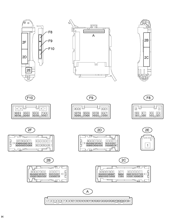
Remove the main body ECU (multiplex network body ECU) (Click here).
Measure the voltage and resistance according to the value(s) in the table below.
| Terminal No. (Symbol) | Wiring Color | Terminal Description | Condition | Specified Condition |
| A-30 (BECU) - Body ground | - | Battery power supply | Always | 11 to 14 V |
| A-31 (ALTB) - Body ground | - | Battery power supply | Always | 11 to 14 V |
| A-32 (IG) - Body ground | - | Ignition switch power supply | Ignition switch ON | 11 to 14 V |
| A-32 (IG) - Body ground | - | Ignition switch power supply | Ignition switch off | Below 1 V |
| A-29 (ACC) - Body ground | - | ACC power supply | Ignition switch ACC | 11 to 14 V |
| A-29 (ACC) - Body ground | - | ACC power supply | Ignition switch off | Below 1 V |
| A-11 (GND1) - Body ground | - | Ground | Always | Below 1 Ω |
| F10-3 (GND2) - Body ground | W-B - Body ground | Ground | Always | Below 1 Ω |
Install the main body ECU (multiplex network body ECU).
Measure the voltage according to the value(s) in the table below.
| Terminal No. (Symbol) | Wiring Color | Terminal Description | Condition | Specified Condition |
| 2F-27 (FLCY) - Body ground | R - Body ground | Front door LH courtesy switch input | Front door LH open | Below 1 V |
| 2F-27 (FLCY) - Body ground | R - Body ground | Front door LH courtesy switch input | Front door LH closed | 11 to 14 V |
| 2B-15 (FRCY) - Body ground | B - Body ground | Front door RH courtesy switch input | Front door RH open | Below 1 V |
| 2B-15 (FRCY) - Body ground | B - Body ground | Front door RH courtesy switch input | Front door RH closed | 11 to 14 V |
| CHECK MULTIPLEX NETWORK DOOR ECU (BACK DOOR P/W) |
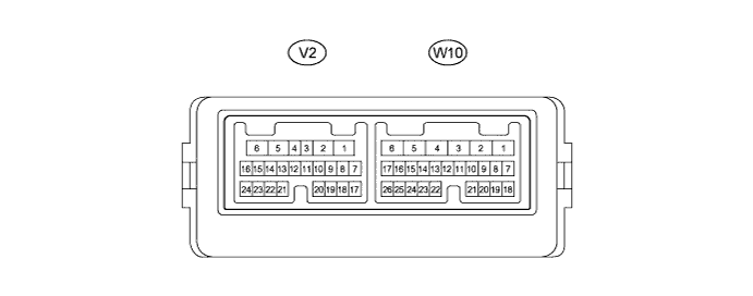
Disconnect the V2 and W10 multiplex network door ECU (back door P/W) connectors.
Measure the voltage and resistance according to the value(s) in the table below.
| Terminal No. (Symbol) | Wiring Color | Terminal Description | Condition | Specified Condition |
| V2-1 (BDR) - Body ground | B - Body ground | Battery power supply | Always | 11 to 14 V |
| V2-7 (BECU) - Body ground | L - Body ground | Battery power supply | Always | 11 to 14 V |
| V2-8 (SIG) - Body ground | G - Body ground | Ignition switch power supply | Ignition switch ON | 11 to 14 V |
| V2-8 (SIG) - Body ground | G - Body ground | Ignition switch power supply | Ignition switch off | Below 1 V |
| V2-6 (GND) - Body ground | W-B - Body ground | Ground | Always | Below 1 Ω |
Reconnect the V2 and W10 multiplex network door ECU (back door P/W) connectors.
Measure the voltage according to the value(s) in the table below.
| Terminal No. (Symbol) | Wiring Color | Terminal Description | Condition | Specified Condition |
| W10-16 (BKL) - W10-8 (KEYE)*1 | P - V | Tail gate control switch lock input | Back door lock key cylinder in neutral position | Pulse generation (See waveform 1 or 2) |
| W10-16 (BKL) - W10-8 (KEYE)*1 | P - V | Tail gate control switch lock input | Back door lock key cylinder in lock position | Below 1 V |
| W10-15 (BKUL) - W10-8 (KEYE)*1 | R - V | Tail gate control switch unlock input | Back door lock key cylinder in neutral position | Pulse generation (See waveform 1 or 2) |
| W10-15 (BKUL) - W10-8 (KEYE)*1 | R - V | Tail gate control switch unlock input | Back door lock key cylinder in unlock position | Below 1 V |
| V2-22 (BUP) - V2-6 (GND) | P -W-B | Back door power window up input | Ignition switch ON, back door power window switch off | Pulse generation (See waveform 3 or 4) |
| V2-22 (BUP) - V2-6 (GND) | P - W-B | Back door power window up input | Ignition switch ON, back door power window switch up | Below 1 V |
| V2-23 (BDN) - V2-6 (GND) | R - W-B | Back door power window up input | Ignition switch ON, back door power window switch off | Pulse generation (See waveform 3 or 4) |
| V2-23 (BDN) - V2-6 (GND) | R - W-B | Back door power window up input | Ignition switch ON, back door power window switch down | Below 1 V |
| W10-24 (HSW+) - W10-7 (HSW-) | GR - LG | Back door opener switch input | Back door opener switch off | Pulse generation (See waveform 5 or 6) |
| W10-24 (HSW+) - W10-7 (HSW-) | GR - LG | Back door opener switch input | Back door opener switch on | Below 1 V |
| W10-17 (SUP) - W10-21 (E3)*2 | W - B | Back door control switch input | Lock switch off | Pulse generation (See waveform 7 or 8) |
| W10-17 (SUP) - W10-21 (E3)*2 | W - B | Back door control switch input | Lock switch on | Below 1 V |
| W10-9 (SDN) - W10-21 (E3)*2 | SB - B | Back door control switch input | Unlock switch off | Pulse generation (See waveform 7 or 8) |
| W10-9 (SDN) - W10-21 (E3)*2 | SB - B | Back door control switch input | Unlock switch on | Below 1 V |
| V2-21 (AUTO) - V2-6 (GND) | B - W-B | Back door power window auto up or auto down input | Ignition switch ON, back door power window switch off | Pulse generation (See waveform 9 or 10) |
| V2-21 (AUTO) - V2-6 (GND) | B - W-B | Back door power window auto up or auto down input | Ignition switch ON, back door power window switch auto up or auto down | Below 1 V |
| V2-3 (W) - V2-12 (SGND) | R - G | Rear wiper reverse position switch input | Ignition switch ON and rear wiper switch on or rear wiper reverse switch off | Pulse generation (See waveform 11) |
| V2-3 (W) - V2-12 (SGND) | R - G | Rear wiper reverse position switch input | Ignition switch ON and rear wiper switch on or rear wiper reverse switch on | Pulse generation (See waveform 12) |
| V2-4 (P) - V2-12 (SGND) | V - G | Rear wiper retractable position switch input | Ignition switch ON and rear wiper switch on or rear wiper retractable position switch off | Pulse generation (See waveform 13) |
| V2-4 (P) - V2-12 (SGND) | V - G | Rear wiper retractable position switch input | Ignition switch ON and rear wiper switch on or rear wiper retractable position switch on | Pulse generation (See waveform 14) |
| W10-14 (BUP2) - W10-1 (E4) | R - LG | Back door power window regulator motor up output | Ignition switch ON, back door power window regulator switch up | Pulse generation (See waveform 15) |
| W10-13 (BDN2) - W10-1 (E4) | B - LG | Back door power window regulator motor down output | Ignition switch ON, back door power window regulator switch down | Pulse generation (See waveform 16) |
| W10-12 (AUT2) - W10-1 (E4) | W - LG | Back door power window regulator motor auto up or auto down output | Ignition switch ON, back door power window auto up or auto down function operating | Pulse generation (See waveform 17) |
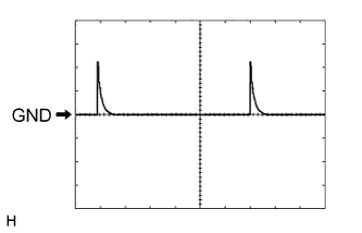 |
Using an oscilloscope, check waveform 1.
| Item | Content |
| Terminal No. (Symbol) |
|
| Tool Setting | 5 V/DIV., 10 ms/DIV. |
| Condition | Back door lock key cylinder in neutral position |
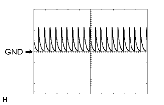 |
Using an oscilloscope, check waveform 2.
| Item | Content |
| Terminal No. (Symbol) |
|
| Tool Setting | 5 V/DIV., 10 ms/DIV. |
| Condition | Back door lock key cylinder in neutral position |
|
Using an oscilloscope, check waveform 3.
| Item | Content |
| Terminal No. (Symbol) |
|
| Tool Setting | 5 V/DIV., 10 ms/DIV. |
| Condition | Ignition switch ON, back door power window switch off |
|
Using an oscilloscope, check waveform 4.
| Item | Content |
| Terminal No. (Symbol) |
|
| Tool Setting | 5 V/DIV., 10 ms/DIV. |
| Condition | Ignition switch ON, back door power window switch off |
|
Using an oscilloscope, check waveform 5.
| Item | Content |
| Terminal No. (Symbol) | W10-24 (HSW+) - W10-7 (HSW-) |
| Tool Setting | 5 V/DIV., 10 ms/DIV. |
| Condition | Back door opener switch off |
|
Using an oscilloscope, check waveform 6.
| Item | Content |
| Terminal No. (Symbol) | W10-24 (HSW+) - W10-7 (HSW-) |
| Tool Setting | 5 V/DIV., 10 ms/DIV. |
| Condition | Back door opener switch off |
|
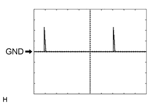
Using an oscilloscope, check waveform 7.
| Item | Content |
| Terminal No. (Symbol) |
|
| Tool Setting | 5 V/DIV., 10 ms/DIV. |
| Condition | Back door control switch off |
|
Using an oscilloscope, check waveform 8.
| Item | Content |
| Terminal No. (Symbol) |
|
| Tool Setting | 5 V/DIV., 10 ms/DIV. |
| Condition | Back door control switch off |
 |
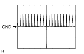
Using an oscilloscope, check waveform 9.
| Item | Content |
| Terminal No. (Symbol) | V2-21 (AUTO) - V2-6 (GND) |
| Tool Setting | 5 V/DIV., 10 ms/DIV. |
| Condition | Ignition switch ON, back door power window switch off |
 |
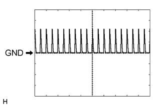
Using an oscilloscope, check waveform 10.
| Item | Content |
| Terminal No. (Symbol) | V2-21 (AUTO) -V2-6 (GND) |
| Tool Setting | 5 V/DIV., 10 ms/DIV. |
| Condition | Ignition switch ON, back door power window switch off |
 |
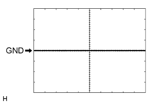
Using an oscilloscope, check waveform 11.
| Item | Content |
| Terminal No. (Symbol) | V2-3 (W) - V2-12 (SGND) |
| Tool Setting | 5 V/DIV., 10 ms/DIV. |
| Condition | Ignition switch ON and rear wiper switch on or rear wiper reverse switch off |
 |
Using an oscilloscope, check waveform 12.
| Item | Content |
| Terminal No. (Symbol) | V2-3 (W) - V2-12 (SGND) |
| Tool Setting | 5 V/DIV., 10 ms/DIV. |
| Condition | Ignition switch ON and rear wiper switch on or rear wiper reverse switch on |
|
Using an oscilloscope, check waveform 13.
| Item | Content |
| Terminal No. (Symbol) | V2-4 (P) - V2-12 (SGND) |
| Tool Setting | 5 V/DIV., 10 ms/DIV. |
| Condition | Ignition switch ON and rear wiper switch on or rear wiper retractable position switch off |
|
Using an oscilloscope, check waveform 14.
| Item | Content |
| Terminal No. (Symbol) | V2-4 (P) - V2-12 (SGND) |
| Tool Setting | 5 V/DIV., 10 ms/DIV. |
| Condition | Ignition switch ON and rear wiper switch on or rear wiper retractable position switch on |
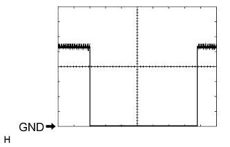 |
Using an oscilloscope, check waveform 15.
| Item | Content |
| Terminal No. (Symbol) | W10-14 (BUP2) - W10-1 (E4) |
| Tool Setting | 2 V/DIV., 100 ms/DIV. |
| Condition | Ignition switch ON, back door power window regulator switch up |
|
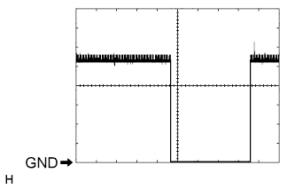
Using an oscilloscope, check waveform 16.
| Item | Content |
| Terminal No. (Symbol) | W10-13 (BDN2) - W10-1 (E4) |
| Tool Setting | 2 V/DIV., 100 ms/DIV. |
| Condition | Ignition switch ON, back door power window regulator switch down |
 |
Using an oscilloscope, check waveform 17.
| Item | Content |
| Terminal No. (Symbol) | W10-12 (AUT2) - W10-1 (E4) |
| Tool Setting | 2 V/DIV., 100 ms/DIV. |
| Condition | Ignition switch ON, back door power window auto up or auto down function operating |