 |
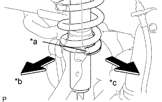
Install the coil spring to the vehicle body with the lower end of the coil spring facing the rear side of the vehicle.
| *a | Lower End |
| *b | Outer Side |
| *c | Rear Side |
FRONT SHOCK ABSORBER > INSTALLATION |
| 1. TEMPORARILY INSTALL FRONT SHOCK ABSORBER WITH COIL SPRING (w/ REAS) |
|
Install the coil spring to the vehicle body with the lower end of the coil spring facing the rear side of the vehicle.
| *a | Lower End |
| *b | Outer Side |
| *c | Rear Side |
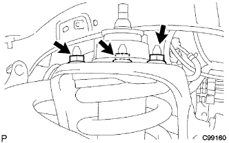 |
Install the 3 nuts to the upper side of the front shock absorber with coil spring.
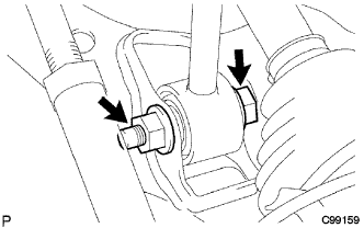 |
Temporarily install the bolt, nut and washer as shown in the illustration.
 |
Install the bolt.
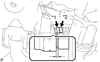 |
As shown in the illustration, tighten the nut so that the clearance reaches the standard value.
| *1 | Turn |
| *2 | Hold |
| 2. TEMPORARILY INSTALL FRONT SHOCK ABSORBER WITH COIL SPRING (w/o REAS) |
|
Install the coil spring to the vehicle body with the lower end of the coil spring facing the rear side of the vehicle.
| *a | Lower End |
| *b | Outer Side |
| *c | Rear Side |
|
Install the 3 nuts to the upper side of the front shock absorber with coil spring.
|
Temporarily install the bolt, nut and washer as shown in the illustration.
| 3. INSTALL FRONT STABILIZER BAR (w/ KDSS) |
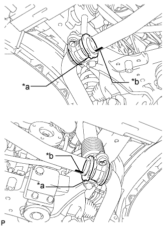 |
Install the 2 front stabilizer lower bracket bushes to the front stabilizer bar.
| *a | Protrusion |
| *b | Mark Position |
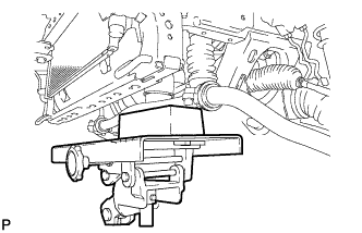 |
With the identification marks of the front stabilizer bar facing downwards, support the front stabilizer bar with a jack.
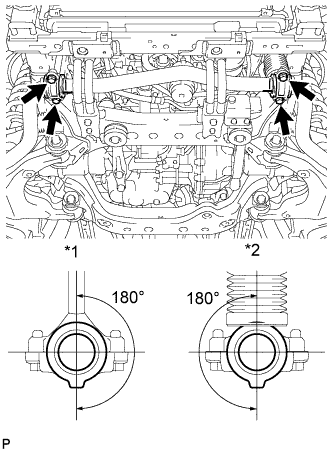 |
Install the front stabilizer bar and 2 front stabilizer lower brackets with the 4 bolts.
| *1 | Stabilizer Link |
| *2 | Stabilizer Cylinder |
| 4. INSTALL FRONT STABILIZER END BRACKET (w/ KDSS) |
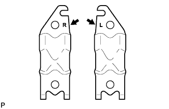 |
Install the 2 front stabilizer brackets and 2 front stabilizer link bushes with the 4 bolts.
| 5. INSTALL FRONT STABILIZER BAR (w/o KDSS) |
| 6. INSTALL FRONT NO. 1 STABILIZER BRACKET LH (w/o KDSS) |
Install the front No. 1 stabilizer bracket LH with the 2 bolts.
| 7. INSTALL FRONT NO. 1 STABILIZER BRACKET RH (w/o KDSS) |
| 8. CONNECT FRONT STABILIZER LINK ASSEMBLY LH (w/o KDSS) |
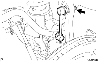 |
Connect the stabilizer link to the steering knuckle with the nut.
| 9. CONNECT FRONT STABILIZER LINK ASSEMBLY RH (w/o KDSS) |
| 10. INSTALL FRONT SUSPENSION MEMBER BRACE SUB-ASSEMBLY |
Install the 2 member braces with the 6 bolts.
| 11. INSTALL NO. 1 ENGINE UNDER COVER SUB-ASSEMBLY |
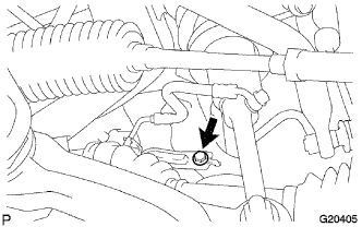
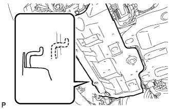 |
Hook the No. 1 engine under cover sub-assembly to the vehicle body as shown in the illustration.
Install the 4 bolts.
| 12. INSTALL LOWER FRONT BUMPER COVER |
Install the front lower bumper cover with the 5 bolts and clip.
| 13. INSTALL FRONT WHEEL |
| 14. STABILIZE SUSPENSION |
Lower the vehicle.
Bounce the vehicle up and down several times to stabilize the suspension.
| 15. TIGHTEN FRONT SHOCK ABSORBER WITH COIL SPRING |
|
Tighten the nut.
| 16. INSPECT AND ADJUST FRONT WHEEL ALIGNMENT |
Inspect and adjust the front wheel alignment (Click here).