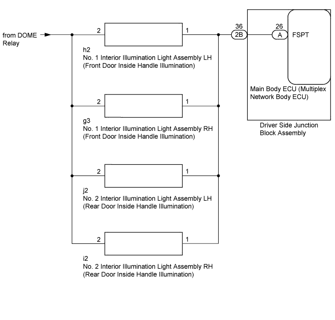
LIGHTING SYSTEM > Inside Handle Illumination Light Circuit |
| 1.CHECK DOOR INSIDE HANDLE ILLUMINATION |
Check the each door inside handle illumination.
| Result | Proceed to |
| Front door inside handle illumination does not come on. | A |
| Rear door inside handle illumination does not come on. | B |
|
| ||||
| A | |
 |
| 2.INSPECT NO. 1 INTERIOR ILLUMINATION LIGHT ASSEMBLY (FRONT DOOR INSIDE HANDLE ILLUMINATION) (LH OR RH) |
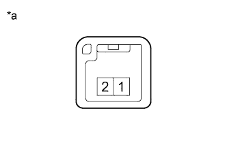 |
Remove the No. 1 interior illumination light assembly (front door inside handle illumination) (Click here).
Connect a positive (+) lead from the battery to terminal 1 and a negative (-) lead to terminal 2.
Check that the No. 1 interior illumination light assembly (front door inside handle illumination) comes on.
| *a | Component without harness connected (No. 1 Interior Illumination Light Assembly (Front Door Inside Handle Illumination)) |
|
| ||||
| OK | |
|
| 3.CHECK HARNESS AND CONNECTOR (BATTERY - NO. 1 INTERIOR ILLUMINATION LIGHT ASSEMBLY) |
Disconnect the h2*1 or g3*2 No. 1 interior illumination light assembly (front door inside handle illumination) connector.
Measure the voltage according to the value(s) in the table below.
| Tester Connection | Condition | Specified Condition |
| h2-2 - Body ground | Always | 11 to 14 V |
| Tester Connection | Condition | Specified Condition |
| g3-2 - Body ground | Always | 11 to 14 V |
|
| ||||
| OK | |
|
| 4.CHECK HARNESS AND CONNECTOR (NO. 1 INTERIOR ILLUMINATION - DRIVER SIDE JUNCTION BLOCK) |
Disconnect the h2*1 or g3*2 No. 1 interior illumination light assembly (front door inside handle illumination) connector.
Disconnect the 2B driver side junction block assembly connector.
Measure the resistance according to the value(s) in the table below.
| Tester Connection | Condition | Specified Condition |
| h2-1 - 2B-36 | Always | Below 1 Ω |
| Tester Connection | Condition | Specified Condition |
| g3-1 - 2B-36 | Always | Below 1 Ω |
| Tester Connection | Condition | Specified Condition |
| h2-1 or 2B-36 - Body ground | Always | 10 kΩ or higher |
| Tester Connection | Condition | Specified Condition |
| g3-1 or 2B-36 - Body ground | Always | 10 kΩ or higher |
| Result | Proceed to |
| NG | A |
| OK | B |
|
| ||||
| A | ||
 | ||
| ||
| 5.INSPECT NO. 2 INTERIOR ILLUMINATION LIGHT ASSEMBLY (REAR DOOR INSIDE HANDLE ILLUMINATION) (LH OR RH) |
|
Remove the No. 2 interior illumination light assembly (rear door inside handle illumination) (Click here ).
Connect a positive (+) lead from the battery to terminal 1 and a negative (-) lead to terminal 2.
Check that the No. 2 interior illumination light assembly (rear door inside handle illumination) comes on.
| *a | Component without harness connected (No. 2 Interior Illumination Light Assembly (Rear Door Inside Handle Illumination)) |
|
| ||||
| OK | |
|
| 6.CHECK HARNESS AND CONNECTOR (BATTERY - NO. 2 INTERIOR ILLUMINATION LIGHT ASSEMBLY) |
Disconnect the j2*1 or i2*2 No. 2 interior illumination light (rear door inside handle illumination) connector.
Measure the voltage according to the value(s) in the table below.
| Tester Connection | Condition | Specified Condition |
| j2-2 - Body ground | Always | 11 to 14 V |
| Tester Connection | Condition | Specified Condition |
| i2-2 - Body ground | Always | 11 to 14 V |
|
| ||||
| OK | |
|
| 7.CHECK HARNESS AND CONNECTOR (NO. 2 INTERIOR ILLUMINATION - DRIVER SIDE JUNCTION BLOCK) |
Disconnect the j2*1 or i2*2 No. 2 interior illumination light (rear door inside handle illumination) connector.
Disconnect the 2B driver side junction block assembly connector.
Measure the resistance according to the value(s) in the table below.
| Tester Connection | Condition | Specified Condition |
| j2-1 - 2B-36 | Always | Below 1 Ω |
| Tester Connection | Condition | Specified Condition |
| i2-1 - 2B-36 | Always | Below 1 Ω |
| Tester Connection | Condition | Specified Condition |
| j2-1 or 2B-36 - Body ground | Always | 10 kΩ or higher |
| Tester Connection | Condition | Specified Condition |
| i2-1 or 2B-36 - Body ground | Always | 10 kΩ or higher |
|
| ||||
| OK | |
|
| 8.INSPECT DRIVER SIDE JUNCTION BLOCK ASSEMBLY |
Remove the driver side junction block assembly (Click here ).
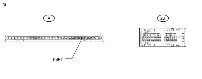
| *a | Component without harness connected (Driver Side Junction Block Assembly) | - | - |
Remove the main body ECU (multiplex network body ECU) from driver side junction block assembly.
Measure the resistance according to the value(s) in the table below.
| Tester Connection | Condition | Specified Condition |
| 2B-36 - A-26 (FSPT) | Always | Below 1 Ω |
|
| ||||
| OK | ||
| ||
| ||

