 |
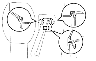
Detach the 2 claws and guide to remove the assist strap hole cover.
BACK DOOR POWER WINDOW MOTOR > REMOVAL |
| 1. DISCONNECT CABLE FROM NEGATIVE BATTERY TERMINAL |
| 2. REMOVE ASSIST STRAP HOLE COVER |
|
Detach the 2 claws and guide to remove the assist strap hole cover.
| 3. REMOVE ASSIST STRAP ASSEMBLY |
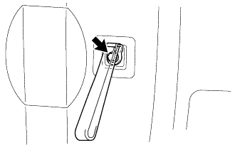 |
Remove the bolt and assist strap assembly.
| 4. REMOVE BACK DOOR TRIM PANEL ASSEMBLY |
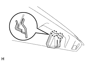 |
Detach the 2 claws to remove the back door lock protector sub-assembly.
| 5. REMOVE REAR NO. 2 SPEAKER ASSEMBLY |
Disconnect the connector.
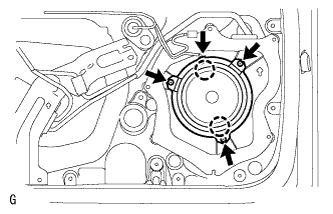 |
Remove the 3 screws.
Detach the 2 claws and remove the speaker.
| 6. REMOVE MULTIPLEX NETWORK DOOR ECU |
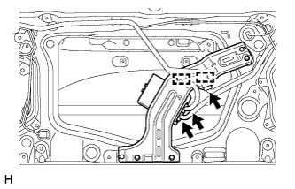 |
Disconnect the 3 connectors to detach the 2 clamps.
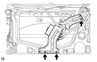 |
Remove the 3 screws.
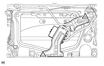 |
Using a clip remover, detach the 2 clips to remove the multiplex network door ECU.
| 7. REMOVE NO. 2 BACK DOOR SERVICE HOLE COVER |
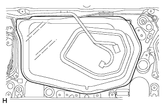 |
Remove the No. 2 back door service hole cover.
| 8. REMOVE BACK DOOR SERVICE HOLE COVER LH |
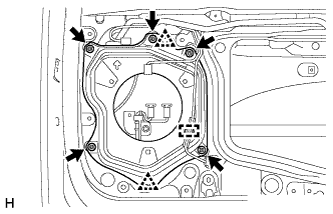 |
Detach the clamp to move the wire harness out of the way.
Remove the 5 screws.
Using a clip remover, detach the 2 clips to remove the back door service hole cover LH.
| 9. REMOVE BACK DOOR SERVICE HOLE COVER RH |
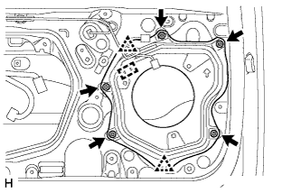 |
Detach the clamp to move the wire harness out of the way.
Remove the 5 screws.
Using a clip remover, detach the 2 clips to remove the back door service hole cover RH.
| 10. REMOVE BACK DOOR OUTSIDE MOULDING LH |
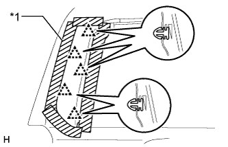 |
Put protective tape around the back door outside moulding.
Detach the 5 clips and remove the back door outside moulding.
| *1 | Protective Tape |
| 11. REMOVE BACK DOOR OUTSIDE MOULDING RH |
| 12. REMOVE REAR NO. 1 SPOILER COVER |
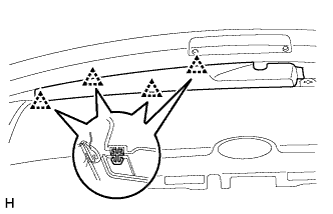 |
Detach the 4 clips and remove the rear No. 1 spoiler cover.
| 13. REMOVE REAR SPOILER SUB-ASSEMBLY |
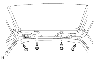 |
Remove the 4 grommets and 4 bolts.
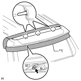 |
Put protective tape around the rear spoiler.
| *1 | Protective Tape |
Disconnect the connector.
Detach the 3 claws and remove the rear spoiler.
| 14. REMOVE REAR WIPER ARM |
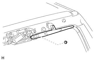 |
Remove the nut and rear wiper blade assembly.
| 15. REMOVE REAR WIPER MOTOR AND BRACKET ASSEMBLY |
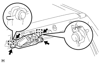 |
Disconnect the connector.
Loosen the 3 bolts.
Detach the 2 guides and remove the rear wiper motor
| 16. REMOVE NO. 1 BACK WINDOW WIPER MOTOR BRACKET |
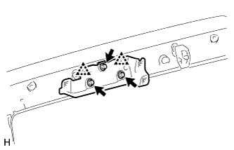 |
Remove the 3 bolts.
Using a clip remover, detach the 2 clips to remove the No. 1 back window wiper motor bracket.
| 17. REMOVE BACK DOOR GLASS RUN |
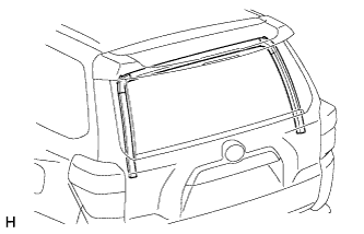 |
Remove the back door glass run.
| 18. REMOVE BACK DOOR GLASS |
Temporarily connect the multiplex network body ECU connectors.
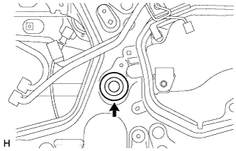 |
Remove the hole plug.
Connect the cable to the negative (-) battery terminal.
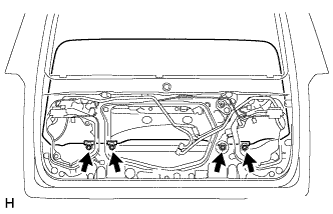 |
Move the back door glass until the 4 bolts can be seen through the service holes.
Disconnect the cable from the negative (-) battery terminal.
Disconnect the multiplex network body ECU connectors.
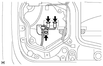 |
Remove the bolt to disconnect the 2 defogger connectors.
|
Remove the 4 bolts.
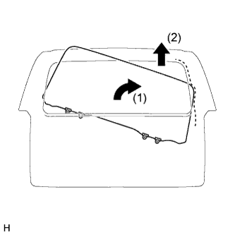 |
Remove the back door glass as shown in the illustration.
Disconnect the rear window connector.
Disconnect the multiplex network door ECU connector.
| 19. REMOVE OUTER BACK DOOR GLASS WEATHERSTRIP ASSEMBLY |
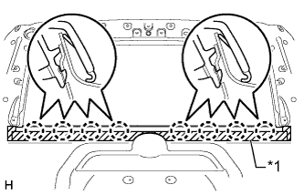 |
Put protective tape around the outer back door glass weatherstrip.
| *1 | Protective Tape |
Detach the 8 claws and remove the outer back door glass weatherstrip.
| 20. REMOVE BACK DOOR POWER WINDOW REGULATOR SUB-ASSEMBLY |
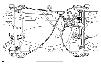 |
Disconnect the power window regulator motor assembly LH connector.
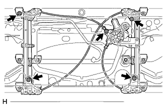 |
Remove the 5 bolts and back door power window regulator sub-assembly.
| 21. REMOVE BACK DOOR POWER WINDOW REGULATOR MOTOR ASSEMBLY |
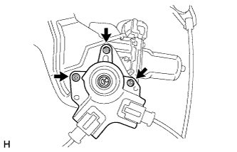 |
Using a T25 "TORX" socket wrench, remove the 3 screws and power window regulator motor.