 |
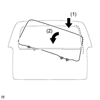
Insert the back door glass as shown in the illustration.
- NOTICE:
- Do not damage the back door glass and back door panel.
BACK DOOR BELT MOULDING > INSTALLATION |
| 1. INSTALL OUTER BACK DOOR GLASS WEATHERSTRIP ASSEMBLY |
Attach the 8 claws to install the outer back door glass weatherstrip.
| 2. INSTALL BACK DOOR GLASS |
Temporarily connect the multiplex network body ECU connectors.
Connect the cable to the negative (-) battery terminal.
Move the back door glass until the bracket can be seen through the service holes.
Disconnect the cable from the negative (-) battery terminal.
Disconnect the multiplex network body ECU connectors.
|
Insert the back door glass as shown in the illustration.
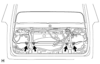 |
Install the back door glass with the 4 bolts.
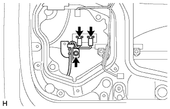 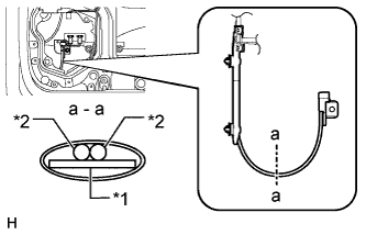 |
Connect the 2 defogger connectors and install the bolt.
| *1 | SUS Plate |
| *2 | Wire Harness |
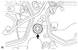 |
Install the hole plug.
| 3. INSTALL BACK DOOR GLASS RUN |
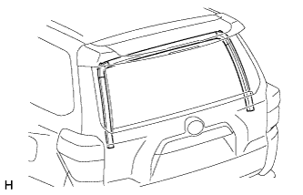 |
Install the back door glass run.
| 4. INSTALL NO. 1 BACK WINDOW WIPER MOTOR BRACKET |
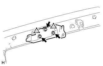 |
Attach the 2 clips to install the No. 1 back window wiper motor bracket.
Install the 3 bolts.
| 5. INSTALL REAR WIPER MOTOR AND BRACKET ASSEMBLY |
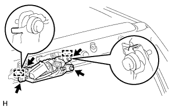 |
Attach the 2 guides and temporally install the rear wiper motor and bracket assembly with the 3 bolts.
Tighten the 3 bolts.
Connect the connector.
| 6. INSTALL REAR WIPER ARM |
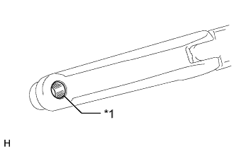 |
Clean the wiper arm serrations.
| *1 | Wiper Arm Pivot Serrations |
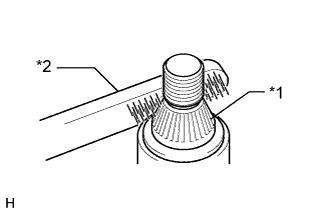 |
Clean the wiper pivot serrations with a wire brush.
| *1 | Wiper Pivot Serrations |
| *2 | Wire Brush |
Operate the rear wiper and stop the rear wiper motor at the automatic stop position.
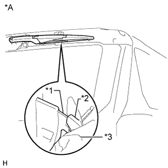 |
With the rear wiper blade and linear wiper step in the positions shown in the illustration, install the rear wiper blade assembly with the nut.
| *A | Tightening Position |
| *1 | Linear Wiper Step |
| *2 | Wiper Blade Rubber Block |
| *3 | Wiper Blade |
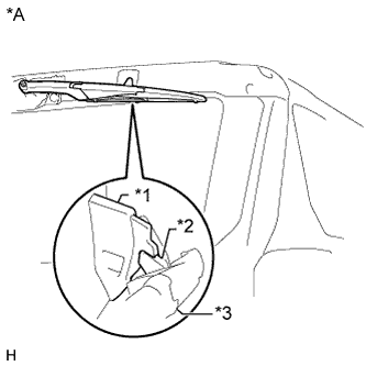 |
Place the rear wiper blade assembly in the automatic stop position.
| *A | Rise-up Position |
| *1 | Linear Wiper Step |
| *2 | Wiper Blade Rubber Block |
| *3 | Wiper Blade |
| 7. INSTALL REAR SPOILER SUB-ASSEMBLY |
Attach the 3 claws to install the rear spoiler.
Connect the connector.
Install the 4 bolts and 4 grommets.
| 8. INSTALL REAR NO. 1 SPOILER COVER |
Attach the 4 clips to install the rear No. 1 spoiler cover.
| 9. INSTALL BACK DOOR OUTSIDE MOULDING LH |
Attach the 5 clips to install the back door outside moulding.
| 10. INSTALL BACK DOOR OUTSIDE MOULDING RH |
| 11. INSTALL BACK DOOR SERVICE HOLE COVER LH |
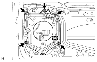 |
Attach the 2 clips to install the back door service hole cover LH.
Install the 5 screws.
Attach the clamp to install the wire harness.
| 12. INSTALL BACK DOOR SERVICE HOLE COVER RH |
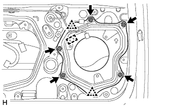 |
Attach the 2 clips to install the back door service hole cover RH.
Install the 5 screws.
Attach the clamp to install the wire harness.
| 13. INSTALL NO. 2 BACK DOOR SERVICE HOLE COVER |
Apply butyl tape to the back door panel.
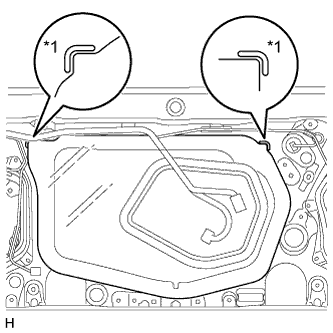 |
Install a new No. 2 back door service hole cover.
| *1 | Reference Point |
Attach the No. 2 back door service hole cover according to the reference points on the back door panel.
| 14. INSTALL MULTIPLEX NETWORK DOOR ECU |
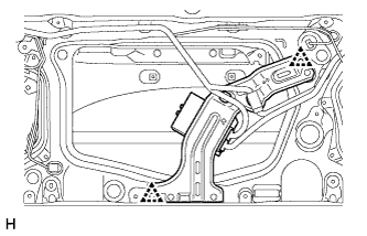 |
Attach the 2 clips to install the multiplex network door ECU to the door panel.
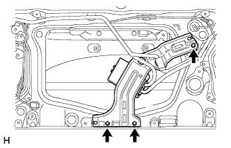 |
Install the 3 screws.
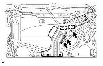 |
Connect the 3 connectors and attach the 2 clamps.
| 15. INSTALL REAR NO. 2 SPEAKER ASSEMBLY |
Temporarily install the speaker by attaching the 2 claws of the speaker to the door panel.
Install the speaker with the 3 screws.
Connect the connector.
| 16. INSTALL BACK DOOR TRIM PANEL ASSEMBLY |
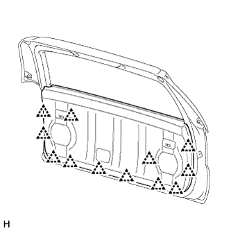 |
Attach the 12 clips to install the back door trim panel assembly.
| 17. INSTALL ASSIST STRAP ASSEMBLY |
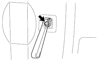 |
Install the assist strap assembly with the bolt.
| 18. INSTALL ASSIST STRAP HOLE COVER |
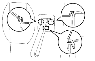 |
Attach the guide and 2 claws to install the assist strap hole cover.
| 19. CONNECT CABLE TO NEGATIVE BATTERY TERMINAL |
| 20. CHECK SRS WARNING LIGHT |
Check the SRS warning light (Click here).