 |
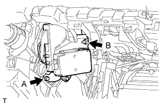
Install the DCM (telematics transceiver) with bracket with the bolt and nut.
- Torque:
- for bolt A:
- 13 N*m{ 133 kgf*cm , 10 ft.*lbf }
- for nut B:
- 12 N*m{ 122 kgf*cm , 9 ft.*lbf }
DCM(TELEMATICS TRANSCEIVER) > INSTALLATION |
| 1. INSTALL NO. 2 TELEPHONE BRACKET |
Install the bracket with the 2 bolts.
| 2. INSTALL NO. 1 TELEPHONE BRACKET |
Install the bracket with the 3 bolts.
Connect the 2 connectors.
| 3. INSTALL MAYDAY BATTERY WITH BRACKET |
Attach the 2 claws to install the mayday battery.
Install the bracket with the bolt.
| 4. INSTALL DCM (TELEMATICS TRANSCEIVER) |
Insert the DCM (telematics transceiver) with bracket into the vehicle.
|
Install the DCM (telematics transceiver) with bracket with the bolt and nut.
Connect the connectors.
| 5. INSTALL LOWER INSTRUMENT PANEL SUB-ASSEMBLY |
Connect each connector.
Attach the 10 clips and guide to install the lower instrument panel sub-assembly.
Install the 3 screws <B> and 2 bolts <C>.
| 6. INSTALL INSTRUMENT PANEL BOX DOOR COVER |
Attach the 2 claws and 2 guides to install the instrument panel box door cover.
| 7. INSTALL LOWER NO. 2 INSTRUMENT PANEL AIRBAG ASSEMBLY |
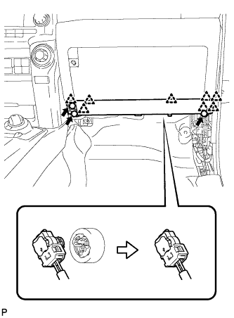 |
Connect the connector.
Attach the 8 claws to install the instrument panel airbag.
Install the 3 bolts.
| 8. INSTALL LOWER INSTRUMENT COVER LH |
Attach the 4 claws to install the lower instrument cover LH.
| 9. INSTALL NO. 2 INSTRUMENT PANEL UNDER COVER SUB-ASSEMBLY |
Attach the 3 clips and 2 guides to install the No. 2 instrument panel under cover sub-assembly.
| 10. INSTALL NO. 2 INSTRUMENT CLUSTER FINISH PANEL GARNISH |
Attach the 5 clips to install the No. 2 instrument cluster finish panel garnish.
| 11. INSTALL COWL SIDE TRIM BOARD RH |
| 12. INSTALL DOOR SCUFF PLATE ASSEMBLY RH |
| 13. CONNECT CABLE TO NEGATIVE BATTERY TERMINAL |
| 14. CHECK SRS WARNING LIGHT |
Check the SRS warning light .
| 15. PERFORM REGISTRATION |
Perform registration (Click here).