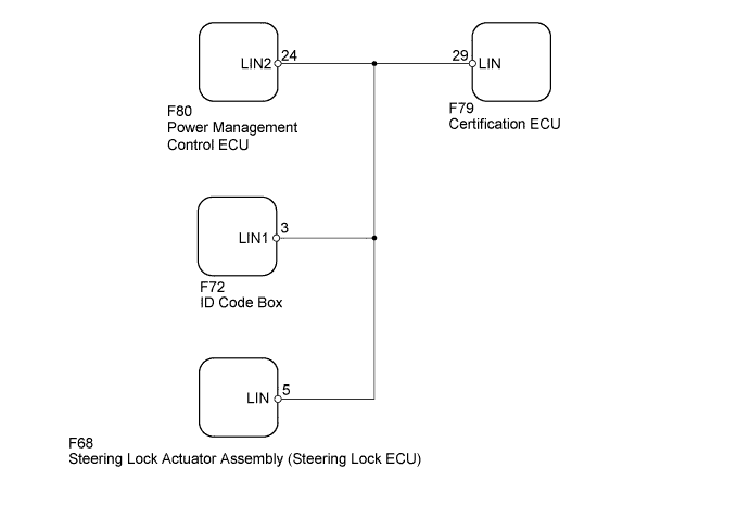
DTC B2785 Communication Malfunction between ECUs Connected by LIN |
| DTC Code | DTC Detection Condition | Trouble Area |
| B2785 | The certification ECU detects a malfunction in the LIN communication bus between components related to certification continuously 3 times. |
|
| 1.CLEAR DTC |
Clear the DTCs (Click here).
| NEXT | |
 |
| 2.CHECK FOR DTC |
Check for DTCs (Click here).
|
| ||||
| OK | ||
 | ||
| ||
| 3.CHECK HARNESS AND CONNECTOR (CERTIFICATION ECU - POWER MANAGEMENT CONTROL ECU) |
Disconnect the F79 certification ECU connector.
Disconnect the F80 power management control ECU connector.
Measure the resistance according to the value(s) in the table below.
| Tester Connection | Condition | Specified Condition |
| F79-29 (LIN) - F80-24 (LIN2) | Always | Below 1 Ω |
| F79-29 (LIN) or F80-24 (LIN2) - Body ground | Always | 10 kΩ or higher |
|
| ||||
| OK | |
|
| 4.CLEAR DTC |
Connect the F79 certification ECU connector.
Disconnect the F80 power management control ECU connector.
Clear the DTCs (Click here).
| NEXT | |
|
| 5.CHECK FOR DTC |
Check for DTCs (Click here).
| Result | Proceed to |
| DTC B2785 is output | A |
| DTC B2785 is not output | B |
|
| ||||
| A | |
|
| 6.CLEAR DTC |
Connect the F80 power management control ECU connector.
Disconnect the F68 steering lock actuator assembly (steering lock ECU) connector.
Clear the DTCs (Click here).
| NEXT | |
|
| 7.CHECK FOR DTC |
Check for DTCs (Click here).
| Result | Proceed to |
| DTC B2785 is output | A |
| DTC B2785 is not output | B |
|
| ||||
| A | |
|
| 8.CLEAR DTC |
Connect the F68 steering lock actuator assembly (steering lock ECU) connector.
Disconnect the F72 ID code box connector.
Clear the DTCs (Click here).
| NEXT | |
|
| 9.CHECK FOR DTC |
Check for DTCs (Click here).
| Result | Proceed to |
| DTC B2785 is output | A |
| DTC B2785 is not output | B |
|
| ||||
| A | ||
| ||
| ||

