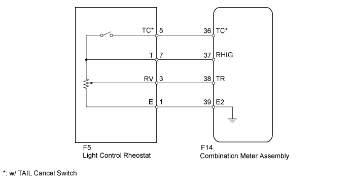
METER / GAUGE SYSTEM > Operating Light Control Rheostat does not Change Light Brightness |
| 1.READ VALUE USING TECHSTREAM (LIGHT CONTROL RHEOSTAT) |
Operate the Techstream according to the display and select the Data List (Click here).
| Tester Display | Measurement Item/Range | Normal Condition | Diagnostic Note |
| Tail Cancel SW* | TAIL cancel switch condition/ON or OFF | ON: TAIL cancel switch on OFF: TAIL cancel switch off | - |
| Rheostat value | Light control rheostat switch input/Min.: 0, Max.: 100 | Light control rheostat switch fully turned downward (0) → fully turned upward (100) | Unit: % |
|
| ||||
| OK | ||
 | ||
| ||
| 2.INSPECT LIGHT CONTROL RHEOSTAT |
Inspect the light control rheostat.
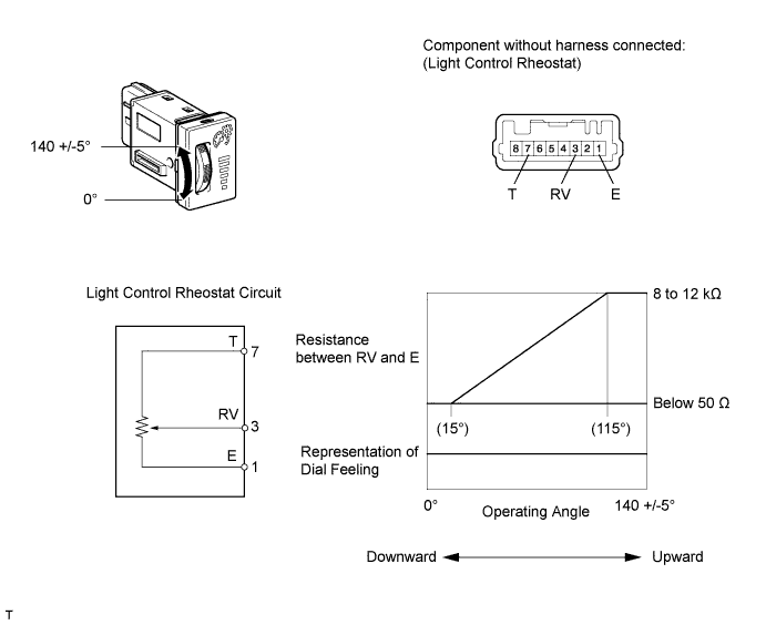
Remove the light control rheostat (Click here).
Measure the resistance according to the table below.
| Tester Connection | Switch Condition | Specified Condition |
| 7 (T) - 1 (E) | Always | 8 to 12 kΩ |
| 3 (RV) - 1 (E) | Light control rheostat fully turned upward → fully turned downward | 8 to 12 kΩ → Below 50 Ω |
Inspect the light control rheostat.
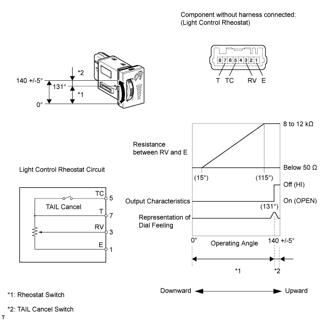
Remove the light control rheostat (Click here).
Measure the resistance according to the table below.
| Tester Connection | Switch Condition | Specified Condition |
| 7 (T) - 5 (TC) | TAIL cancel switch off → on | 1 MΩ or higher → Below 1 Ω |
| 7 (T) - 1 (E) | Always | 8 to 12 kΩ |
| 3 (RV) - 1 (E) | Light control rheostat fully turned upward → fully turned downward | 8 to 12 kΩ → Below 50 Ω |
|
| ||||
| OK | |
 |
| 3.CHECK HARNESS AND CONNECTOR (COMBINATION METER - LIGHT CONTROL RHEOSTAT) |
Disconnect the F14 meter connector.
Disconnect the F5 rheostat connector.
Measure the resistance according to the value(s) in the table below.
| Tester Connection | Condition | Specified Condition |
| F14-36 (TC) - F5-5 (TC)* | Always | Below 1 Ω |
| F14-37 (RHIG) - F5-7 (T) | ||
| F14-38 (TR) - F5-3 (RV) | ||
| F14-39 (E2) - F5-1 (E) |
|
| ||||
| OK | |
|
| 4.REPLACE COMBINATION METER ASSEMBLY |
Replace the combination meter assembly with a new or normally functioning one. Perform an operation inspection.
|
| ||||
| OK | ||
| ||
| ||

