 |
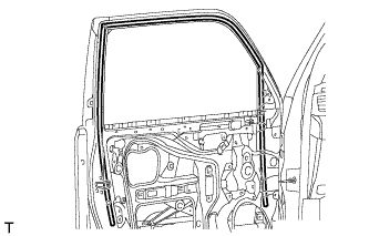
Install the front door glass run LH.
FRONT DOOR BELT MOULDING > INSTALLATION |
| 1. INSTALL FRONT DOOR BELT MOULDING LH |
Attach the 6 claws to install the front door belt moulding.
| 2. INSTALL FRONT DOOR GLASS RUN LH |
|
Install the front door glass run LH.
| 3. INSTALL FRONT DOOR GLASS SUB-ASSEMBLY LH |
Connect the multiplex network master switch assembly (for Driver Side).
Connect the power window regulator switch assembly (for Front Passenger Side).
Connect the cable to the negative (-) battery terminal.
Move the front door glass sub-assembly so that the front door glass bolts can be seen.
Disconnect the cable from the negative (-) battery terminal.
Disconnect the multiplex network master switch assembly (for Driver Side).
Disconnect the power window regulator switch assembly (for Front Passenger Side).
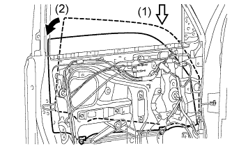 |
Insert the front door glass sub-assembly LH into the front door panel along the front door glass run LH as indicated by the arrows in the order shown in the illustration.
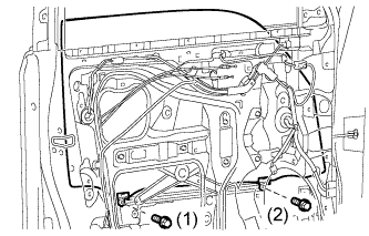 |
Install the front door glass sub-assembly LH with the 2 bolts in the order shown in the illustration.
| 4. INSTALL OUTER REAR VIEW MIRROR ASSEMBLY LH |
Attach the claw to install the outer rear view mirror assembly LH.
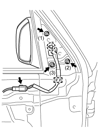 |
Install the 3 nuts in the order shown in the illustration.
Attach the clamp.
Connect the connector.
| 5. INSTALL FRONT DOOR SERVICE HOLE COVER LH |
Apply a new butyl tape to the front door panel.
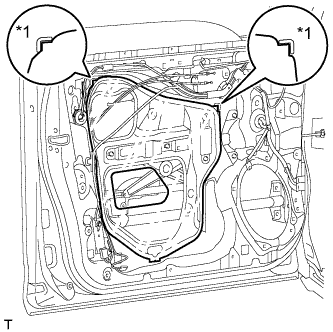 |
Pass the front door lock remote control cable assembly LH and front door inside locking cable assembly LH through a new front door service hole cover LH.
Install a new front door service hole cover LH according to the reference points on the front door panel.
| *1 | Reference Point |
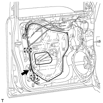 |
Attach the 2 clamps.
Connect the door wire with the bolt.
| 6. INSTALL FRONT DOOR INNER GLASS WEATHERSTRIP LH |
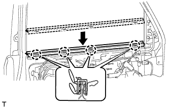 |
Attach the 4 claws to install the front door inner glass weatherstrip LH as shown in the illustration.
| 7. INSTALL FRONT DOOR TRIM BOARD SUB-ASSEMBLY LH |
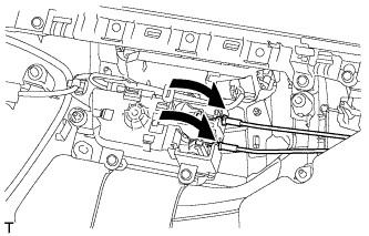 |
Connect the front door lock remote control cable assembly LH and front door inside locking cable assembly LH.
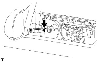 |
Connect the connector.
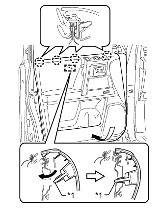 |
Attach the front door trim board sub-assembly LH to the 4 claws of the front door inner glass weatherstrip LH as shown in the illustration.
Attach the reference boss.
| *1 | Reference Boss |
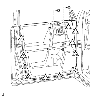 |
Attach the 11 clips to install the front door trim board sub-assembly LH.
Install the 3 screws.
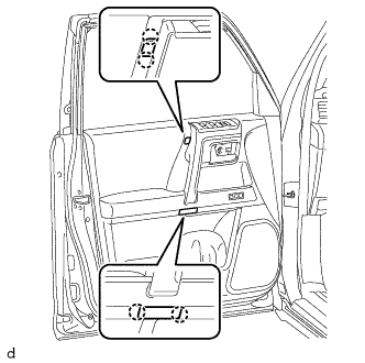 |
Attach the 4 claws to install the 2 door armrest caps.
| 8. INSTALL NO. 2 DOOR INSIDE HANDLE BEZEL LH |
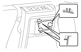 |
Attach the 3 claws to install the No. 2 door inside handle bezel LH.
| 9. INSTALL FRONT DOOR LOWER FRAME BRACKET GARNISH LH |
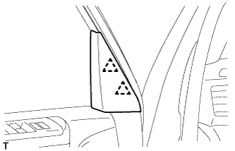 |
Attach the 2 clips to install the front door lower frame bracket garnish LH.
| 10. CONNECT CABLE TO NEGATIVE BATTERY TERMINAL |
| 11. CHECK SRS WARNING LIGHT |
Check the SRS warning light (Click here).