 |
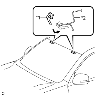
Install 2 new No. 1 windshield glass stoppers to the vehicle body as shown in the illustration.
| *1 | No. 1 Windshield Glass Stopper |
| *2 | Vehicle Body |
WINDSHIELD GLASS > INSTALLATION |
| 1. INSTALL NO. 1 WINDSHIELD GLASS STOPPER |
|
Install 2 new No. 1 windshield glass stoppers to the vehicle body as shown in the illustration.
| *1 | No. 1 Windshield Glass Stopper |
| *2 | Vehicle Body |
| 2. INSTALL NO. 2 WINDSHIELD GLASS STOPPER |
Apply Primer G to the windshield glass where the No. 2 windshield glass stoppers will be installed.
Install 2 new No. 2 windshield glass stoppers to the windshield glass at the locations shown in the illustration.
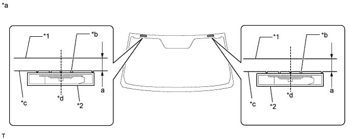
| *1 | Windshield Glass | *2 | No. 2 Windshield Glass Stopper |
| *a | Backside | *b | Ceramic Notch |
| *c | Ceramic Line | d | Center |
| Area | Specified Condition |
| a | 14.2 mm (0.559 in.) |
| 3. INSTALL WINDSHIELD OUTSIDE UPPER MOULDING |
Using a brush or sponge, coat the contact surface of the windshield glass and windshield outside upper moulding with Primer G as shown in the illustration.
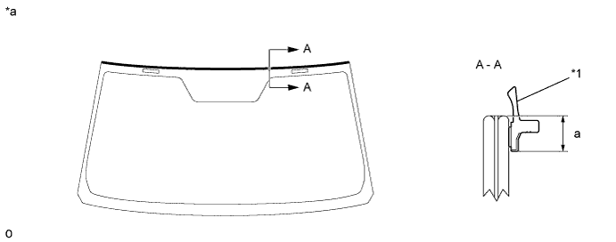
| *1 | Windshield Outside Upper Moulding | - | - |
| *a | Backside | - | - |
| Area | Specified Condition |
| a | 6.9 mm (0.272 in.) |
Remove the peeling paper from a new windshield outside upper moulding. Install the windshield outside upper moulding as shown in the illustration.
| 4. INSTALL WINDSHIELD GLASS ADHESIVE DAM |
Apply Primer G to the windshield glass where the windshield glass adhesive dam will be installed.
Remove the peeling paper from the adhesive part of a new windshield glass adhesive dam. Install the windshield glass adhesive dam (adhesive side) to the windshield glass (Primer G area), but exclude the area above the notches on the upper part of the windshield glass.
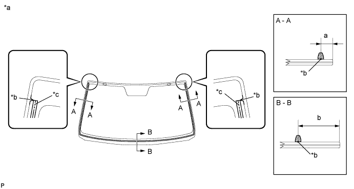
| *a | Backside | *b | Ceramic Notch |
| *c | Dam Center Line | - | - |
| Area | Specified Condition |
| a | 9.5 mm (0.374 in.) |
| b | 37.7 mm (1.48 in.) |
| 5. INSTALL WINDSHIELD GLASS |
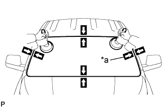 |
Position the windshield glass.
Using suction cups, place the windshield glass in the correct position.
Check that the entire contact surface of the windshield glass rim is perfectly even.
Place matchmarks on the windshield glass and vehicle body at the locations indicated in the illustration.
| *a | Matchmark |
Using suction cups, remove the windshield glass.
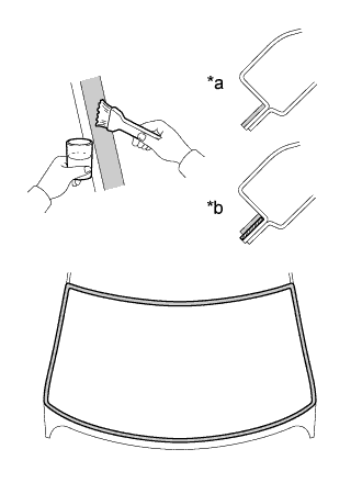 |
Using a brush, apply Primer M to the exposed part of the vehicle body.
| *a | CORRECT |
| *b | INCORRECT |
 | Primer M |
 | Adhesive |
Using a brush or sponge, apply Primer G to the contact surface of the windshield glass.
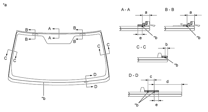
| *a | Backside | *b | Adhesive Center Line |
| Primer M | - | - |
| Area | Specified Condition |
| a | 9.5 mm (0.374 in.) |
| b | 3.0 mm (0.118 in.) |
| c | 8.0 mm (0.315 in.) |
| d | 28.1 mm (1.11 in.) |
| e | 7.0 mm (0.276 in.) |
Apply adhesive to the windshield glass.
Cut off the tip of a cartridge nozzle as shown in the illustration.
| Temperature | Usage Time Frame |
| 35°C (95°F) | 15 minutes |
| 20°C (68°F) | 1 hour 40 minutes |
| 5°C (41°F) | 8 hours |
Load a sealer gun with the cartridge.
Apply adhesive to the windshield glass as shown in the illustration.
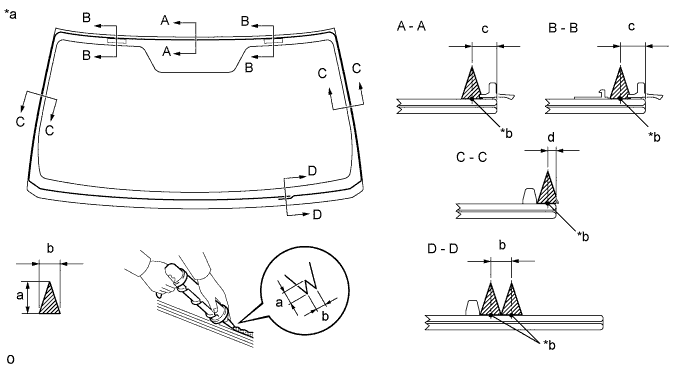
| *a | Backside | *b | Adhesive Center Line |
| Adhesive | - | - |
| Area | Specified Condition |
| a | 12.0 mm (0.472 in.) |
| b | 8.0 mm (0.315 in.) |
| c | 9.5 mm (0.374 in.) |
| d | 3.0 mm (0.118 in.) |
|
Install the windshield glass to the vehicle body.
Using suction cups, position the windshield glass so that the matchmarks are aligned. Press it in gently along the rim.
| *a | Matchmark |
Lightly press the outer surface of the windshield glass to ensure that it is securely fit to the vehicle body.
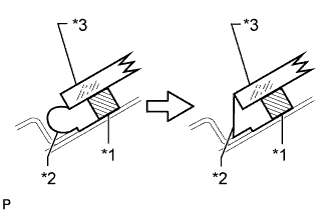 |
If necessary, use a scraper to correct the level or position of adhesive that has been applied.
| *1 | Windshield Glass Adhesive Dam |
| *2 | Adhesive |
| *3 | Windshield Glass |
Hold the windshield glass in place securely with protective tape or equivalent until the adhesive hardens.
| Temperature | Minimum Time Prior to Driving Vehicle |
| 35°C (95°F) | 1 hour 30 minutes |
| 20°C (68°F) | 5 hours |
| 5°C (41°F) | 24 hours |
w/ Windshield Deicer System:
Connect the windshield deicer connector.
| 6. INSTALL WINDSHIELD OUTSIDE MOULDING |
Using a brush or sponge, apply Primer G to the windshield glass where the windshield outside moulding will be installed.
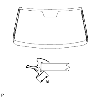 |
Apply Primer G to the windshield outside moulding area "a" shown in the illustration.
Install a new windshield outside moulding to the windshield glass as shown in the illustration.
| 7. CHECK FOR LEAK AND REPAIR |
Conduct a leak test after the adhesive has completely hardened.
Seal any leaks with auto glass sealer.
| 8. INSTALL ROOF HEADLINING ASSEMBLY |
Return the roof headlining assembly to its original position. Refer to the following procedures (Click here).
| 9. INSTALL INNER REAR VIEW MIRROR ASSEMBLY (w/ EC Mirror) |
Using a T20 "TORX" socket wrench, install the inner rear view mirror assembly with the screw.
Connect the connector.
| 10. INSTALL INNER REAR VIEW MIRROR STAY HOLDER COVER (w/ EC Mirror) |
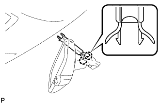 |
Attach the 2 claws to install the inner rear view mirror stay holder cover.
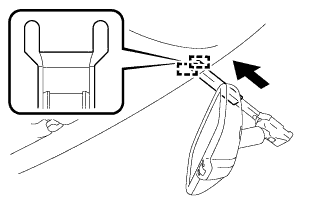 |
Attach the 2 guides to install the inner rear view mirror stay holder cover as shown in the illustration.
| 11. INSTALL INNER REAR VIEW MIRROR ASSEMBLY (w/o EC Mirror) |
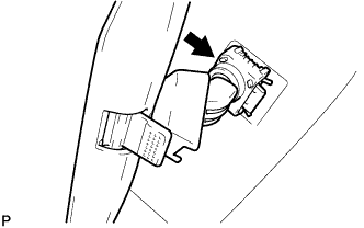 |
Slide and install the inner rear view mirror assembly as shown in the illustration.
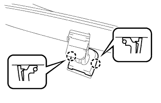 |
Attach the 2 claws to install the cover.
| 12. INSTALL MAP LIGHT ASSEMBLY |
Connect the connector.
Attach the 2 clips to install the map light assembly.
Install the 2 screws.
Close the cover (w/o Drive Monitor Switch).
| 13. INSTALL DRIVE MONITOR SWITCH (w/ Drive Monitor Switch) |
Connect the connector.
Attach the 4 claws to install the drive monitor switch.
| 14. INSTALL VISOR HOLDER |
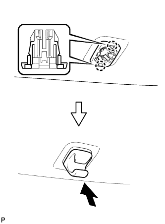 |
Attach the 2 claws.
Push in the visor holder to install it.
| 15. INSTALL VISOR ASSEMBLY LH |
Install the visor assembly LH with the 2 screws.
| 16. INSTALL VISOR ASSEMBLY RH |
| 17. INSTALL VISOR BRACKET COVER LH |
Attach the 4 claws to install the visor bracket cover LH.
| 18. INSTALL VISOR BRACKET COVER RH |
| 19. INSTALL ASSIST GRIP SUB-ASSEMBLY |
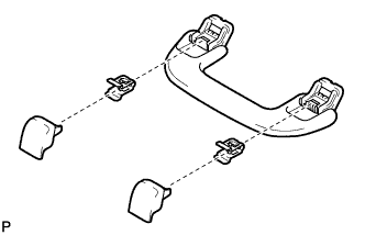 |
Assemble the assist grip sub-assembly as shown in the illustration.
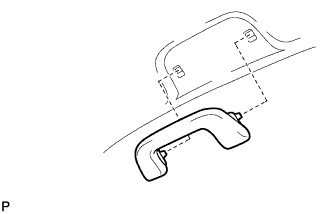 |
Install the assist grip sub-assembly.
| 20. INSTALL FRONT PILLAR GARNISH LH |
Remove the protective cover.
Attach the 2 guides and clip to install the front pillar garnish LH.
Install the bolt.
Attach the 2 claws to install the No. 1 front pillar garnish cover LH.
| 21. INSTALL FRONT PILLAR GARNISH RH |
Remove the protective cover.
Attach the clip and 3 guides to install the front pillar garnish RH.
| 22. INSTALL NO. 1 ASSIST GRIP |
Attach the 2 claws to install the No. 1 assist grip.
Install the 2 bolts.
| 23. INSTALL ASSIST GRIP PLUG |
Attach the 2 claws to install the assist grip plug.
| 24. INSTALL FRONT DOOR OPENING TRIM WEATHERSTRIP LH |
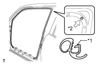 |
Align the paint mark on the front door opening trim weatherstrip LH with the mark position on the vehicle to install the front door opening trim weatherstrip LH as shown in the illustration.
| *1 | Paint Mark |
| *2 | Mark Position |
| 25. INSTALL FRONT DOOR OPENING TRIM WEATHERSTRIP RH |
| 26. INSTALL COWL SIDE TRIM BOARD LH |
Attach the clip and claw to install the cowl side trim board LH.
Install the clip.
| 27. INSTALL COWL SIDE TRIM BOARD RH |
| 28. INSTALL DOOR SCUFF PLATE ASSEMBLY LH |
Attach the 4 clips, 10 claws and 2 guides to install the door scuff plate assembly LH.
| 29. INSTALL DOOR SCUFF PLATE ASSEMBLY RH |
| 30. INSTALL COWL TOP VENTILATOR LOUVER SUB-ASSEMBLY |
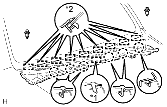 |
Attach the 9 guides (B).
| *1 | Guide A |
| *2 | Guide B |
Attach the 6 claws and guide (A) as shown in the illustration.
Install the 2 clips to the cowl top ventilator louver sub-assembly.
| 31. INSTALL FRONT WIPER ARM AND BLADE ASSEMBLY RH |
Operate the wiper and stop the windshield wiper motor at the automatic stop position.
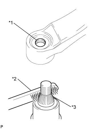 |
When reusing the front wiper arm and blade assembly RH:
Clean the wiper arm serrations.
| *1 | Wiper Arm Serration |
| *2 | Wire Brush |
| *3 | Wiper Pivot Serration |
When reusing the windshield wiper link assembly:
Clean the wiper pivot serrations with a wire brush.
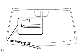 |
Install the front wiper arm and blade assembly RH to the position shown in the illustration with the nut.
| *1 | Ceramic Dot |
| 32. INSTALL FRONT WIPER ARM AND BLADE ASSEMBLY LH |
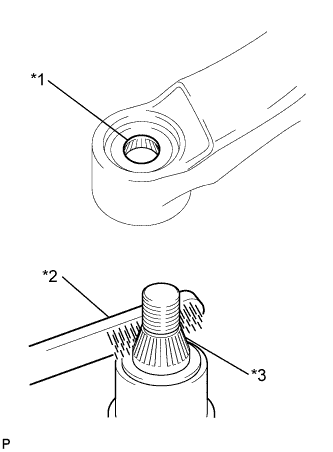 |
When reusing the front wiper arm and blade assembly LH:
Clean the wiper arm serrations.
| *1 | Wiper Arm Serration |
| *2 | Wire Brush |
| *3 | Wiper Pivot Serration |
When reusing the windshield wiper link assembly:
Clean the wiper pivot serrations with a wire brush.
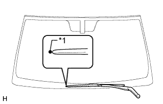 |
Install the front wiper arm and blade assembly LH to the position shown in the illustration with the nut.
| *1 | Ceramic Dot |
Operate the front wipers while spraying washer fluid on the windshield glass. Make sure that the front wipers function properly and there is no interference with the vehicle body.
| 33. INSTALL FRONT WIPER ARM HEAD CAP |
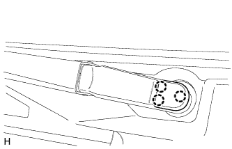 |
Attach the 3 claws to install the front wiper arm head cap.
| 34. INSTALL FRONT FENDER TO COWL SIDE SEAL LH |
Attach the 5 claws to install the front fender to cowl side seal LH.
| 35. INSTALL FRONT FENDER TO COWL SIDE SEAL RH |
| 36. INSTALL FRONT FENDER MAIN SEAL LH |
Attach the 4 clips and 2 guides.
| 37. INSTALL FRONT FENDER MAIN SEAL RH |
| 38. INSTALL UPPER RADIATOR SUPPORT SEAL |
Install the upper radiator support seal with the 13 clips.
| 39. CONNECT CABLE TO NEGATIVE BATTERY TERMINAL |