 |
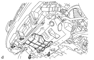
Remove the 4 clips and cool air intake duct.
CAMSHAFT > REMOVAL |
| 1. DISCONNECT CABLE FROM NEGATIVE BATTERY TERMINAL |
| 2. REMOVE COOL AIR INTAKE DUCT (for 4WD with Intuitive Parking Assist System) |
|
Remove the 4 clips and cool air intake duct.
| 3. REMOVE FRONT LOWER BUMPER COVER (w/o Intuitive Parking Assist System) |
Remove the clip, 5 bolts and front lower bumper cover.
| 4. REMOVE FRONT LOWER BUMPER COVER (w/ Intuitive Parking Assist System) |
Remove the clip, 4 bolts and front lower bumper cover.
| 5. REMOVE AIR INTAKE DUCT LH (w/ Intuitive Parking Assist System) |
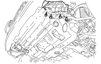 |
Remove the clip and bolt.
Remove the 2 screws and air intake duct LH.
| 6. REMOVE AIR INTAKE DUCT RH (w/ Intuitive Parking Assist System) |
| 7. REMOVE NO. 1 ENGINE UNDER COVER SUB-ASSEMBLY |
Remove the 4 bolts.
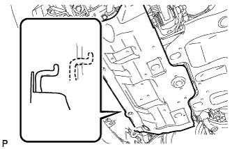 |
Unhook the No. 1 engine under cover sub-assembly from the vehicle body as shown in the illustration.
| 8. DRAIN ENGINE OIL |
Remove the oil filler cap.
Remove the oil pan drain plug and drain the engine oil into a container.
Install a new gasket and the oil pan drain plug.
| 9. DRAIN ENGINE COOLANT |
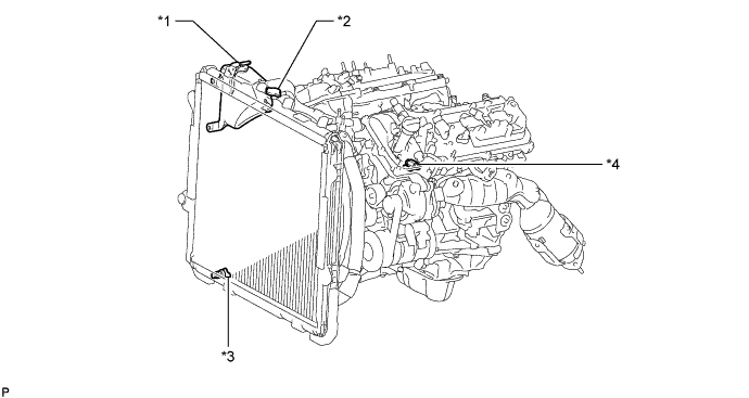
| *1 | Reservoir Cap | *2 | Radiator Cap |
| *3 | Radiator Drain Cock Plug | *4 | Cylinder Block Drain Cock Plug (RH side) |
Loosen the radiator drain cock plug.
Remove the radiator cap and drain the coolant.
Loosen the cylinder block drain cock plug and drain the coolant from the engine.
| 10. REMOVE UPPER RADIATOR SUPPORT SEAL |
Remove the 13 clips and upper radiator support seal.
| 11. DISCONNECT CABLE FROM POSITIVE BATTERY TERMINAL |
| 12. REMOVE BATTERY HOLD DOWN CLAMP |
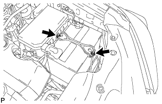 |
Loosen the 2 nuts and remove the battery clamp.
| 13. REMOVE BATTERY |
| 14. REMOVE BATTERY TRAY |
| 15. REMOVE V-BANK COVER |
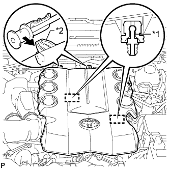 |
Raise the front of the V-bank cover to detach the 2 pins. Then detach the 2 V-bank cover hooks from the bracket, and remove the V-bank cover.
| *1 | Pin |
| *2 | V-bank Cover Hook |
| 16. REMOVE AIR CLEANER CAP AND HOSE |
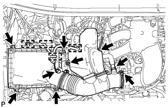 |
Remove the air cleaner cap and hose.
Disconnect the mass air flow meter connector, vacuum hose and ventilation hose and detach the 4 clamps.
Loosen the clamp.
Unfasten the 4 hook clamps, and then remove the bolt and air cleaner cap and hose.
| 17. REMOVE AIR CLEANER CASE SUB-ASSEMBLY |
Remove the air cleaner filter element sub-assembly.
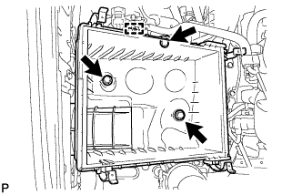 |
Detach the wire harness clamp.
Remove the 3 bolts and air cleaner case sub-assembly.
| 18. REMOVE NO. 1 RADIATOR HOSE |
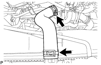 |
Loosen the 2 clamps and remove the No. 1 radiator hose.
| 19. REMOVE NO. 2 RADIATOR HOSE |
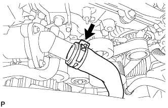 |
Loosen the clamp and disconnect the No. 2 radiator hose from the water inlet.
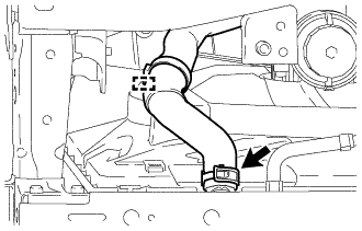 |
Detach the clamp from the fan shroud.
Loosen the clamp and remove the No. 2 radiator hose.
| 20. REMOVE RADIATOR RESERVOIR TANK |
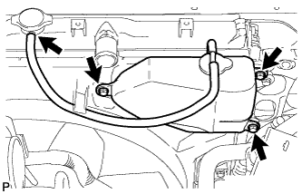 |
Disconnect the reservoir hose from the upper side of the radiator tank.
Remove the 3 bolts and radiator reservoir tank.
| 21. DISCONNECT OIL COOLER TUBE |
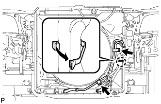 |
Detach the claw to open the flexible hose clamp, and then remove the 2 bolts to disconnect the oil cooler tube from the fan shroud.
| 22. REMOVE FAN SHROUD |
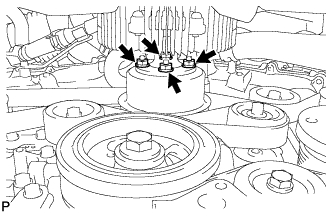 |
Loosen the 4 nuts holding the fan with fluid coupling.
Remove the fan with fluid coupling and generator V-belt (Click here).
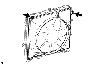 |
Remove the 2 bolts holding the fan shroud.
Remove the 4 nuts of the fan with fluid coupling, and then remove the shroud together with the fan with fluid coupling.
Remove the fan pulley from the water pump.
| 23. REMOVE AIR TUBE ASSEMBLY |
for Bank 1 Side:
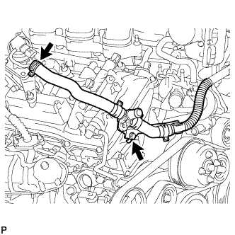 |
Remove the bolt and disconnect the air tube assembly from the No. 1 emission control valve set.
for Bank 2 Side:
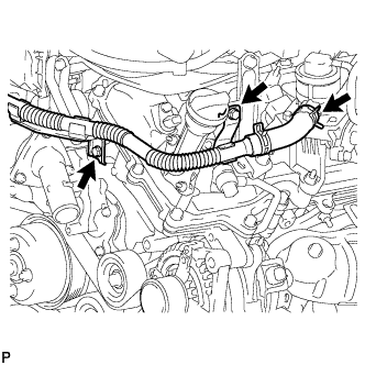 |
Remove the 2 bolts and disconnect the air tube assembly from the No. 2 emission control valve set.
| 24. REMOVE INTAKE AIR SURGE TANK |
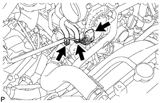 |
Disconnect the throttle body connector.
Disconnect the No. 4 water by-pass hose.
Disconnect the No. 5 water by-pass hose.
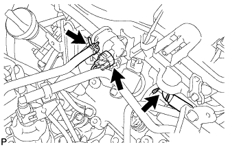 |
Disconnect the No. 1 fuel vapor feed hose.
Disconnect the No. 1 vacuum switching valve connector.
Disconnect the No. 1 ventilation hose.
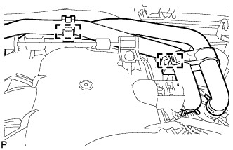 |
Detach the 2 heater hose clamps.
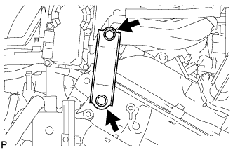 |
Remove the 2 bolts and throttle body bracket.
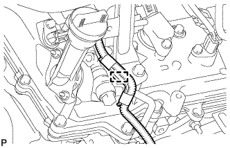 |
Using a clip remover, detach the wire harness clamp.
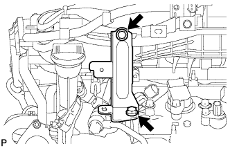 |
Remove the 2 bolts and No. 1 surge tank stay.
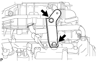 |
Remove the 2 bolts and No. 2 surge tank stay.
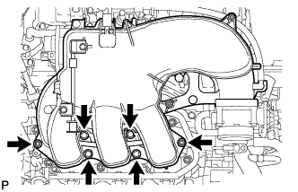 |
Remove the 2 nuts, 4 bolts and intake air surge tank.
Remove the gasket.
| 25. REMOVE AIR TUBE |
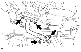 |
Remove the 2 bolts, 2 nuts and air tube.
Remove the 2 gaskets from the air tube.
| 26. REMOVE NO. 2 AIR TUBE |
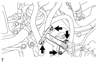 |
Remove the 2 bolts, 2 nuts and No. 2 air tube.
Remove the 2 gaskets from the No. 2 air tube.
| 27. REMOVE NO. 1 EMISSION CONTROL VALVE SET |
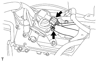 |
Disconnect the No. 1 emission control valve set connector.
Disconnect the No. 1 air hose from the No. 1 emission control valve set.
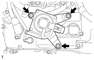 |
Remove the 3 nuts and No. 1 emission control valve set.
| 28. REMOVE NO. 2 EMISSION CONTROL VALVE SET |
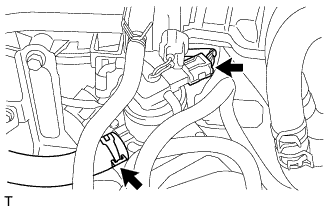 |
Disconnect the No. 2 emission control valve set connector.
Disconnect the No. 3 air hose.
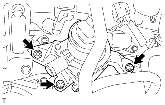 |
Remove the 3 nuts and No. 2 emission control valve set.
| 29. REMOVE IGNITION COIL ASSEMBLY |
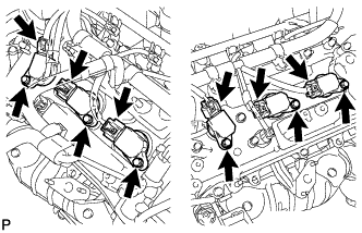 |
Disconnect the 6 ignition coil assembly connectors.
Remove the 6 bolts and 6 ignition coil assemblies.
| 30. DISCONNECT VANE PUMP ASSEMBLY |
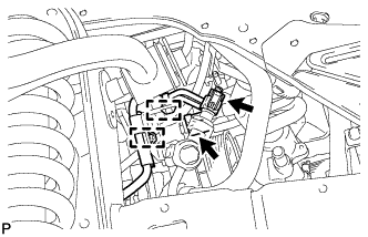 |
Disconnect the 2 connectors.
Detach the 2 wire harness clamps.
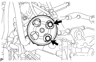 |
Remove the 2 bolts and disconnect the vane pump assembly.
| 31. REMOVE NO. 2 IDLER PULLEY SUB-ASSEMBLY |
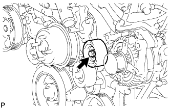 |
for Integrated Type:
Remove the bolt and No. 2 idler pulley.
for Separate Type:
Remove the bolt, No. 2 idler pulley cover plate, No. 2 idler pulley and idler pulley cover plate.
| 32. REMOVE WIRING HARNESS CLAMP BRACKET |
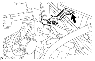 |
Detach the clamp.
Remove the bolt and wiring harness clamp bracket.
| 33. REMOVE NO. 2 EXHAUST MANIFOLD HEAT INSULATOR |
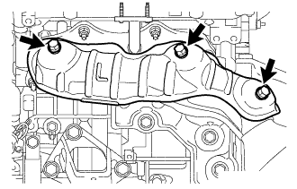 |
Remove the 3 bolts and No. 2 exhaust manifold heat insulator.
| 34. REMOVE GENERATOR ASSEMBLY |
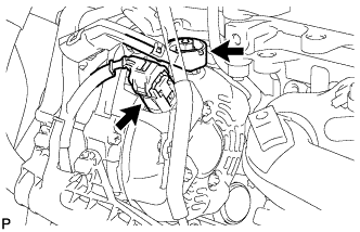 |
Open the terminal cap.
Remove the nut and disconnect the wire harness from terminal B.
Disconnect the generator connector from the generator assembly.
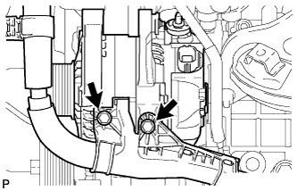 |
Remove the 2 bolts and disconnect the wire harness.
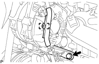 |
Disconnect the wire harness clamp.
Remove the bolt and disconnect the generator bracket.
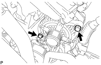 |
Remove the 2 bolts and generator assembly.
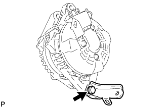 |
Remove the bolt and generator bracket.
| 35. REMOVE ENGINE OIL LEVEL DIPSTICK GUIDE |
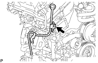 |
Remove the engine oil level dipstick.
Remove the bolt and engine oil level dipstick guide.
Remove the O-ring from the engine oil level dipstick guide.
| 36. REMOVE WATER BY-PASS PIPE SUB-ASSEMBLY |
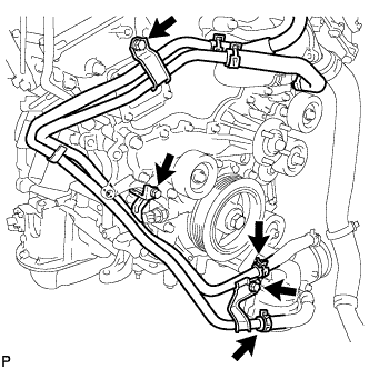 |
Disconnect the 2 hoses.
Remove the 3 bolts and water by-pass pipe sub-assembly.
| 37. REMOVE NO. 1 OIL PIPE |
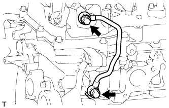 |
Remove the 2 oil pipe unions, oil control valve filter LH, 3 gaskets and No. 1 oil pipe.
| 38. REMOVE NO. 2 OIL PIPE |
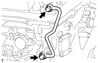 |
Remove the 2 oil pipe unions, oil control valve filter RH, 3 gaskets and No. 2 oil pipe.
| 39. REMOVE REAR CYLINDER HEAD COVER |
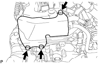 |
Remove the 3 bolts and cover.
| 40. DISCONNECT FUEL PIPE SUB-ASSEMBLY |
Remove the 2 bolts and disconnect the fuel pipe sub-assembly.
| 41. REMOVE CYLINDER HEAD COVER SUB-ASSEMBLY LH |
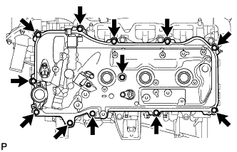 |
Remove the 12 bolts, seal washer, cylinder head cover sub-assembly LH and gasket.
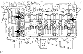 |
Remove the 3 gaskets.
| 42. REMOVE CYLINDER HEAD COVER SUB-ASSEMBLY |
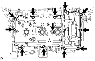 |
Remove the 12 bolts, seal washer, cylinder head cover sub-assembly and gasket.
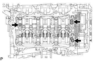 |
Remove the 3 gaskets.
| 43. REMOVE TIMING CHAIN COVER PLATE |
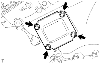 |
Remove the 4 bolts, timing chain cover plate and gasket.
| 44. SET NO. 1 CYLINDER TO TDC/COMPRESSION |
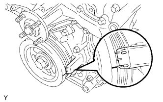 |
Turn the crankshaft pulley and align the notch with the "0" timing mark of the timing chain cover sub-assembly.
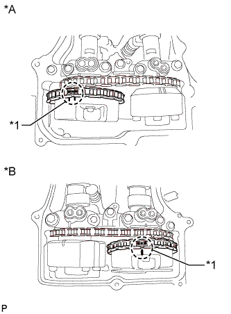 |
Check that the timing marks of the camshaft timing gears are aligned with the timing marks of the bearing caps as shown in the illustration.
| *A | for Bank 2 |
| *B | for Bank 1 |
| *1 | Paint Mark |
Place paint marks on the timing marks and sprockets of each camshaft timing gear and on the links of the chain sub-assembly.
| 45. REMOVE NO. 1 CHAIN TENSIONER ASSEMBLY |
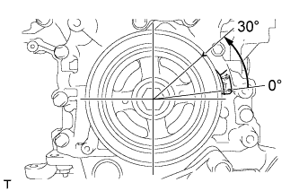 |
Turn the crankshaft approximately 30° counterclockwise so that there is some slack in the chain sub-assembly.
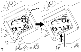 |
Align the hole in the lever of the No. 1 chain tensioner assembly with the hole in the No. 1 chain tensioner assembly body as shown in the illustration, and then insert a pin with a diameter of 1.27 mm (0.0500 in.) into the hole.
| *1 | Lever Hole |
| *2 | Tensioner Hole |
|
Turn the crankshaft clockwise and align the notch with the "0" timing mark of the timing chain cover sub-assembly.
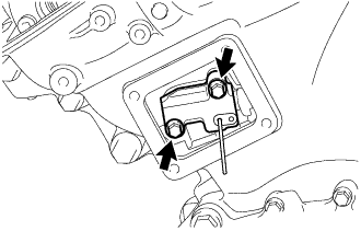 |
Remove the 2 bolts and No. 1 chain tensioner assembly.
| 46. DISCONNECT CHAIN SUB-ASSEMBLY (for Bank 1) |
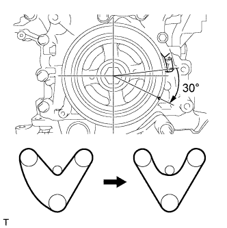 |
Turn the crankshaft clockwise until it is in the position shown in the illustration so that there is some slack in the chain sub-assembly between the banks.
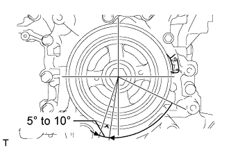 |
Turn the crankshaft clockwise until it is in the position shown in the illustration so that the chain sub-assembly can be removed easily.
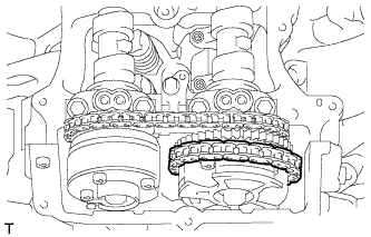 |
Remove the chain sub-assembly from the sprocket of the camshaft timing gear and set it on the gear.
| 47. REMOVE CAMSHAFT BEARING CAP (for Bank 1) |
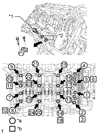 |
Remove the bolts and bearing caps in the order shown in the illustration. Immediately after removing a bearing cap, install bolts and washers for temporary installation of the camshaft housing in the order shown in the illustration.
| *1 | Bolt |
| *2 | Washer |
| *a | Part Removal |
| *b | Installation of Bolts and Washers for Temporary Installation of camshaft housing |
| 48. REMOVE NO. 2 CAMSHAFT |
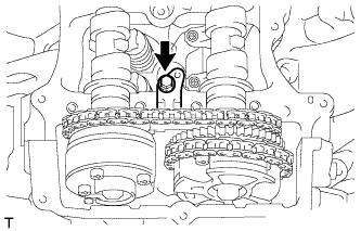 |
Remove the bolt of the No. 2 chain tensioner assembly.
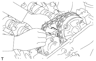 |
Remove the No. 2 chain tensioner assembly while lifting up the No. 2 camshaft.
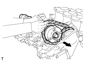 |
While lifting up the No. 2 camshaft, pass it through the No. 2 chain and pull it out towards the front of the vehicle to remove it.
| 49. REMOVE CAMSHAFT |
Lift up the rear of the camshaft so that it is at an angle.
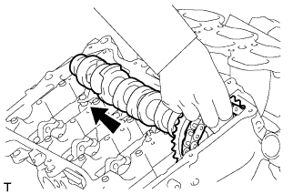 |
Remove the chain sub-assembly from the camshaft timing gear and pull out the camshaft and chain sub-assembly towards the rear of the vehicle to remove them.
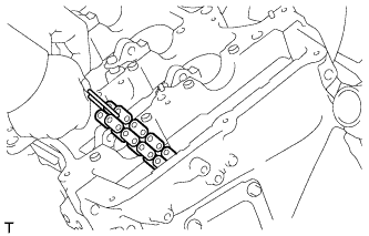 |
Suspend the chain sub-assembly with a string or equivalent.
| 50. DISCONNECT CHAIN SUB-ASSEMBLY (for Bank 2) |
|
Turn the crankshaft counterclockwise and align the notch with the "0" timing mark of the timing chain cover sub-assembly.
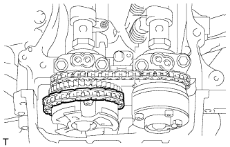 |
Remove the chain sub-assembly from the sprocket of the camshaft timing gear and set it on the gear.
| 51. REMOVE CAMSHAFT BEARING CAP (for Bank 2) |
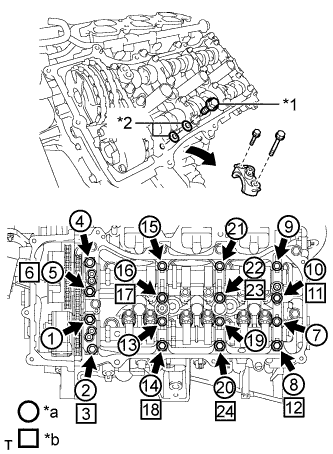 |
Remove the bolts and bearing caps in the order shown in the illustration. Immediately after removing a bearing cap, install bolts and washers for temporary installation of the camshaft housing in the order shown in the illustration.
| *1 | Bolt |
| *2 | Washer |
| *a | Part Removal |
| *b | Installation of Bolts and Washers for Temporary Installation of camshaft housing |
| 52. REMOVE NO. 4 CAMSHAFT |
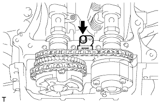 |
Remove the bolt of the No. 3 chain tensioner assembly.
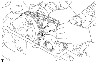 |
Remove the No. 3 chain tensioner assembly while lifting up the No. 4 camshaft.
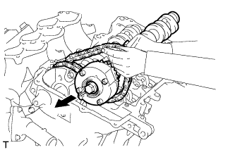 |
While lifting up the No. 4 camshaft, pass it through the chain sub-assembly and pull it out towards the front of the vehicle to remove it.
| 53. REMOVE NO. 3 CAMSHAFT |
Lift up the rear of the No. 3 camshaft so that it is at an angle.
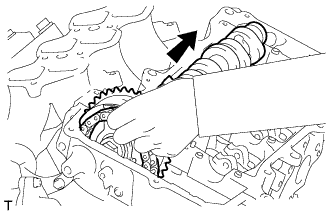 |
Remove the chain sub-assembly from the camshaft timing gear and pull out the No. 3 camshaft and chain sub-assembly towards the rear of the vehicle to remove them.
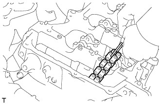 |
Suspend the chain sub-assembly with a string or equivalent.
| 54. REMOVE CAMSHAFT TIMING GEAR ASSEMBLY |
Fix the camshaft in place.
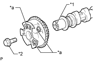 |
Remove the flange bolt and camshaft timing gear assembly.
| *1 | Straight Pin |
| *2 | Flange Bolt |
| *a | Do not remove |
| 55. REMOVE CAMSHAFT TIMING EXHAUST GEAR ASSEMBLY |
Fix the camshaft in place.
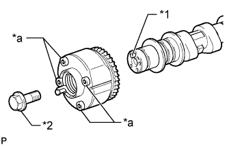 |
Remove the flange bolt and camshaft timing exhaust gear assembly.
| *1 | Straight Pin |
| *2 | Flange Bolt |
| *a | Do not remove |