 |
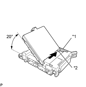
Insert the multiplex network body ECU until it contacts the housing sidewall of the guide part as shown in the illustration.
| *1 | Housing Sidewall |
| *2 | Guide Part |
- HINT:
- Be sure to maintain an angle of 20° or more as shown in the illustration.
MAIN BODY ECU > INSTALLATION |
| 1. INSTALL MULTIPLEX NETWORK BODY ECU |
|
Insert the multiplex network body ECU until it contacts the housing sidewall of the guide part as shown in the illustration.
| *1 | Housing Sidewall |
| *2 | Guide Part |
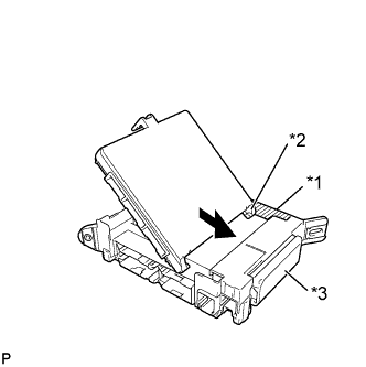 |
Slide the guide of the multiplex network body ECU along the housing sidewall toward the junction block fuses as shown in the illustration.
| *1 | Housing Sidewall |
| *2 | Guide Part |
| *3 | Junction Block Fuse |
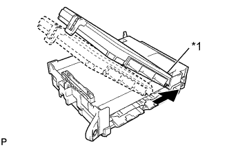 |
Slide the multiplex network body ECU so that it contacts side A as shown in the illustration.
| *1 | Side A |
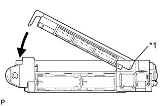 |
With the multiplex network body ECU contacting side A of the junction block (point of rotation), rotate it downward as shown in the illustration.
| *1 | Side A Contact Portion |
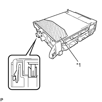 |
Press the pushing area until the claw attaches to install the multiplex network body ECU.
| *1 | Pushing Area |
| 2. INSTALL DRIVER SIDE JUNCTION BLOCK ASSEMBLY |
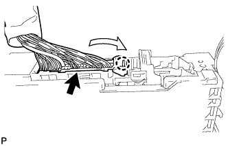 |
Attach the claw to install the connector as shown in the illustration.
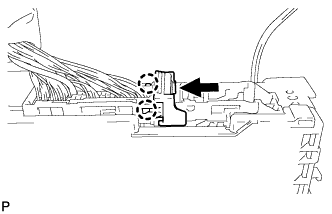 |
Attach the 2 claws to lock the connector lock as shown in the illustration.
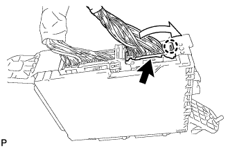 |
Attach the claw to connect the connector as shown in the illustration.
Install the driver side junction block assembly with the bolt and 2 nuts.
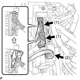 |
Connect the connector labeled (2).
Connect the 2 connectors labeled (1) as shown in the illustration.
Connect the 3 connectors.
| 3. INSTALL LOWER NO. 1 INSTRUMENT PANEL AIRBAG ASSEMBLY |
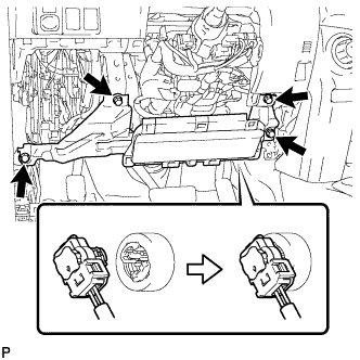 |
Connect the connector.
Install the airbag assembly with the 4 bolts.
| 4. INSTALL LOWER INSTRUMENT PANEL FINISH PANEL SUB-ASSEMBLY |
Connect each connector and hood lock control cable assembly.
Attach the 13 clips and 2 guides to install the lower instrument panel finish panel sub-assembly.
Install the 2 bolts <C>.
Attach the 2 claws to close the cover.
| 5. INSTALL NO. 1 INSTRUMENT CLUSTER FINISH PANEL GARNISH |
Attach the 5 clips to install the No. 1 instrument cluster finish panel garnish.
| 6. INSTALL COWL SIDE TRIM BOARD LH |
Attach the clip and claw to install the cowl side trim board LH.
Install the clip.
| 7. INSTALL DOOR SCUFF PLATE ASSEMBLY LH |
Attach the 4 clips, 10 claws and 2 guides to install the door scuff plate assembly LH.
| 8. CONNECT CABLE TO NEGATIVE BATTERY TERMINAL |
| 9. CHECK SRS WARNING LIGHT |
Check the SRS warning light (Click here).