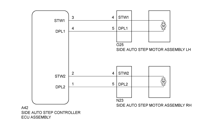
DTC 22 Open in Motor LH Circuit |
DTC 24 Open in Motor RH Circuit |
| DTC No. | Detection Condition | Trouble Area |
| 22 | Open in the stowing or deploying side of the side auto step motor LH circuit. |
|
| 24 | Open in the stowing or deploying side of the side auto step motor RH circuit. |
| 1.CHECK HARNESS AND CONNECTOR (SIDE AUTO STEP MOTOR - SIDE AUTO STEP CONTROLLER ECU) |
Disconnect the O25*1 or N23*2 side auto step motor assembly connector.
Disconnect the A42 side auto step controller ECU assembly connector.
Measure the resistance according to the value(s) in the table below.
| Tester Connection | Condition | Specified Condition |
| O25-4 (STW1) - A42-3 (STW1) | Always | Below 5 Ω |
| O25-5 (DPL1) - A42-4 (DPL1) | Always | Below 5 Ω |
| Tester Connection | Condition | Specified Condition |
| N23-4 (STW2) - A42-2 (STW2) | Always | Below 5 Ω |
| N23-5 (DPL2) - A42-1 (DPL1) | Always | Below 5 Ω |
|
| ||||
| OK | ||
 | ||
| ||
