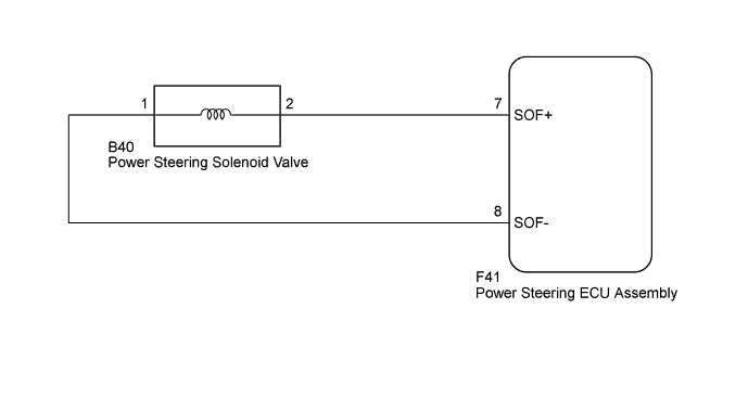
DTC C15F0 VFC Solenoid Circuit |
| DTC Code | DTC Detection Condition | Trouble area |
| C15F0 | A short or open in the solenoid valve circuit. |
|
| 1.READ VALUE USING TECHSTREAM (SOLENOID CURRENT) |
Turn the ignition switch off.
Connect the Techstream to the DLC3.
Turn the ignition switch to ON.
Turn the Techstream on.
Enter the following menus: Chassis / PPS / Data List.
| Tester Display | Measurement Item/Range | Normal Condition | Diagnostic Note |
| Solenoid Current | Solenoid Current/ Min.: 0 mA Max.: 1000 mA | 200 to 950 mA | The engine is running and the steering wheel is being turned. |
|
| ||||
| OK | ||
 | ||
| ||
| 2.CHECK HARNESS AND CONNECTOR (POWER STEERING ECU ASSEMBLY - POWER STEERING SOLENOID VALVE) |
Disconnect the F41 power steering ECU assembly connector.
Disconnect the B40 power steering solenoid valve connector.
Measure the resistance according to the value(s) in the table below.
| Tester Connection | Condition | Specified Condition |
| F41-7 (SOF+) - B40-2 | Always | Below 1 Ω |
| F41-8 (SOF-) - B40-1 | ||
| F41-7 (SOF+) or B40-2 - Body ground | Always | 10 kΩ or higher |
| F41-8 (SOF-) or B40-1 - Body ground |
|
| ||||
| OK | |
 |
| 3.INSPECT POWER STEERING SOLENOID VALVE ASSEMBLY |
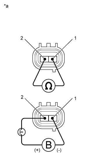 |
Disconnect the B40 power steering solenoid valve connector.
Measure the resistance according to the value(s) in the table below.
| Tester Connection | Condition | Specified Condition |
| 1 - 2 | 20°C (68°F) | 6.7 to 7.3 Ω |
Connect the positive (+) lead of the battery with a 21 W bulb to terminal 2 and the negative (-) lead to terminal 1 of the solenoid valve connector. Then check that the valve moves and makes an operating noise.
| *a | Component without harness connected (Power Steering Solenoid Valve) |
|
| ||||
| OK | ||
| ||
| ||

