Home › Engine / Hybrid System › 1GR-FE INTAKE / EXHAUST › EXHAUST MANIFOLD

EXHAUST MANIFOLD > INSTALLATION

for Preparation Click here


1. INSTALL AIR FUEL RATIO SENSOR (for Bank 2 Sensor 1)


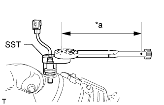
    A223685E01
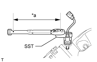
  1. Using SST, install the air fuel ratio sensor to the exhaust manifold sub-assembly LH.

    SST
    09224-00010  

    Torque:
    without SST:
    44 N*m{ 449 kgf*cm , 32 ft.*lbf }
    with SST:
    40 N*m{ 408 kgf*cm , 30 ft.*lbf }

    Text in Illustration 
    *a
    Fulcrum Length

    NOTICE:
    Do not use the air fuel ratio sensor if it has been subjected to physical shocks, such as being dropped, etc.

    HINT:
    1. Use a torque wrench with a fulcrum length of 30 cm (11.8 in.). When using a torque wrench with a fulcrum length that is not 30 cm (11.8 in.), calculate the torque specification for the torque wrench and SST based on the "without SST" torque specification (Click here).
    2. Make sure SST and the wrench are connected in a straight line.


2. INSTALL EXHAUST MANIFOLD SUB-ASSEMBLY LH


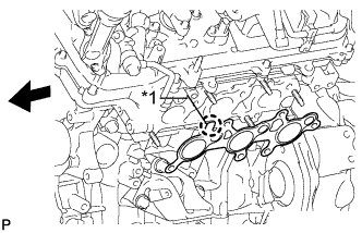
    A222094E01
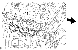
  1. Install a new gasket onto the cylinder head.
    Text in Illustration 
    *1
    Protrusion
    V100135
    Front

    NOTICE:
    Be careful of the installation direction.

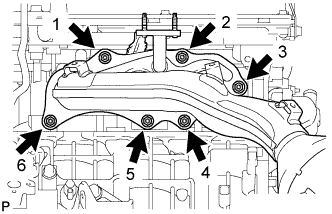
  1. Temporarily install the exhaust manifold sub-assembly LH with 6 new nuts.


    A222092E02
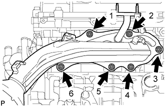
  1. Tighten the 6 nuts in the sequence shown in the illustration.

    Torque:
    21 N*m{ 214 kgf*cm , 15 ft.*lbf }

  1. Connect the air fuel ratio sensor connector.


3. INSTALL NO. 2 EXHAUST MANIFOLD HEAT INSULATOR
  1. Install the No. 2 exhaust manifold heat insulator with the 3 bolts.

    Torque:
    13 N*m{ 133 kgf*cm , 10 ft.*lbf }


4. INSTALL NO. 2 AIR TUBE


    A289303E01
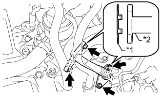
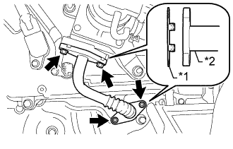
  1. Install 2 new gaskets to the No. 2 air tube.
    Text in Illustration 
    *1
    New Gasket
    *2
    No. 2 Air Tube

    NOTICE:
    Be careful not to damage the installation surfaces of the gaskets.

  1. Install the No. 2 air tube with the 2 bolts and 2 nuts.

    Torque:
    10 N*m{ 102 kgf*cm , 7 ft.*lbf }


5. INSTALL MANIFOLD STAY
  1. Install the manifold stay with the 3 bolts.

    Torque:
    40 N*m{ 408 kgf*cm , 30 ft.*lbf }


6. INSTALL AIR FUEL RATIO SENSOR (for Bank 1 Sensor 1)


    A223683E01
  1. Using SST, install the air fuel ratio sensor to the exhaust manifold sub-assembly RH.

    SST
    09224-00010  

    Torque:
    without SST:
    44 N*m{ 449 kgf*cm , 32 ft.*lbf }
    with SST:
    40 N*m{ 408 kgf*cm , 30 ft.*lbf }

    Text in Illustration 
    *a
    Fulcrum Length

    NOTICE:
    Do not use the air fuel ratio sensor if it has been subjected to physical shocks, such as being dropped, etc.

    HINT:
    1. Use a torque wrench with a fulcrum length of 30 cm (11.8 in.). When using a torque wrench with a fulcrum length that is not 30 cm (11.8 in.), calculate the torque specification for the torque wrench and SST based on the "without SST" torque specification (Click here).
    2. Make sure SST and the wrench are connected in a straight line.


7. INSTALL EXHAUST MANIFOLD SUB-ASSEMBLY RH


    A222095E01
  1. Install a new gasket onto the cylinder head.
    Text in Illustration 
    *1
    Protrusion
    V100135
    Front

    NOTICE:
    Be careful of the installation direction.

  1. Temporarily install the exhaust manifold sub-assembly RH with 6 new nuts.


    A222089E02
  1. Tighten the 6 nuts in the sequence shown in the illustration.

    Torque:
    21 N*m{ 214 kgf*cm , 15 ft.*lbf }

  1. Connect the air fuel ratio sensor connector.


8. INSTALL NO. 1 EXHAUST MANIFOLD HEAT INSULATOR
  1. Install the No. 1 exhaust manifold heat insulator with the 3 bolts.

    Torque:
    13 N*m{ 133 kgf*cm , 10 ft.*lbf }


9. INSTALL AIR TUBE


    A289302E01
  1. Install 2 new gaskets to the air tube.
    Text in Illustration 
    *1
    New Gasket
    *2
    Air Tube

    NOTICE:
    Be careful not to damage the installation surfaces of the gaskets.

  1. Install the air tube with the 2 bolts and 2 nuts.

    Torque:
    10 N*m{ 102 kgf*cm , 7 ft.*lbf }


10. INSTALL NO. 2 MANIFOLD STAY
  1. Install the manifold stay with the 3 bolts.

    Torque:
    40 N*m{ 408 kgf*cm , 30 ft.*lbf }


11. INSTALL FRONT EXHAUST PIPE ASSEMBLY
(Click here)


12. INSTALL AIR CLEANER CASE SUB-ASSEMBLY
  1. Install the air cleaner case sub-assembly with the 3 bolts.

    Torque:
    12 N*m{ 122 kgf*cm , 9 ft.*lbf }

  1. Attach the wire harness clamp.

  1. Install the air cleaner filter element sub-assembly.


13. INSTALL AIR CLEANER CAP AND HOSE


    A223697E01
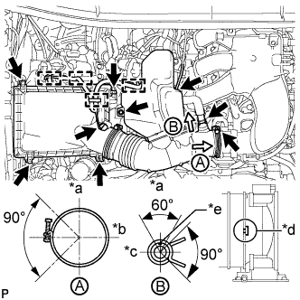
  1. Install the air cleaner cap and hose.
    Text in Illustration 
    *a
    Upper
    *b
    Front
    *c
    RH
    *d
    Align cutout portion of hose with protrusion of throttle
    *e
    Paint Mark

    1. Install the air cleaner cap and hose with the bolt and fasten the 4 hook clamps.

      Torque:
      5.0 N*m{ 51 kgf*cm , 44 in.*lbf }

    2. Tighten the clamp.

      Torque:
      5.0 N*m{ 51 kgf*cm , 44 in.*lbf }

    3. Attach the 4 clamps and connect the ventilation hose, vacuum hose and mass air flow meter connector.

      HINT:
      The direction of the hose clamp is indicated in the illustration.


14. INSTALL V-BANK COVER


    A229926E01
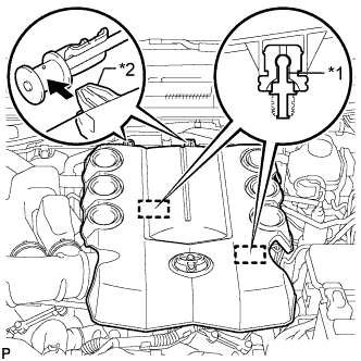
  1. Attach the 2 V-bank cover hooks to the bracket. Then align the 2 V-bank cover grommets with the 2 pins and press down on the V-bank cover to attach the pins.
    Text in Illustration 
    *1
    Pin
    *2
    V-bank Cover Hook


15. INSTALL UPPER RADIATOR SUPPORT SEAL
  1. Install the upper radiator support seal with the 13 clips.


16. INSPECT FOR EXHAUST GAS LEAK
  1. If gas is leaking, tighten the areas necessary to stop the leak. Replace damaged parts as necessary.


17. INSTALL FRONT FENDER APRON SEAL LH
  1. w/ KDSS:
    Install the front fender apron seal LH with the 7 clips.

  1. w/o KDSS:
    Install the front fender apron seal LH with the 5 clips.


18. INSTALL FRONT FENDER APRON SEAL RH
  1. Install the front fender apron seal RH with the 4 clips.


19. INSTALL FRONT NO. 1 FENDER APRON TO FRAME SEAL LH
  1. Install the front No. 1 fender apron to frame seal LH with the 5 clips.


20. INSTALL FRONT NO. 1 FENDER APRON TO FRAME SEAL RH
  1. Install the front No. 1 fender apron to frame seal RH with the 5 clips.