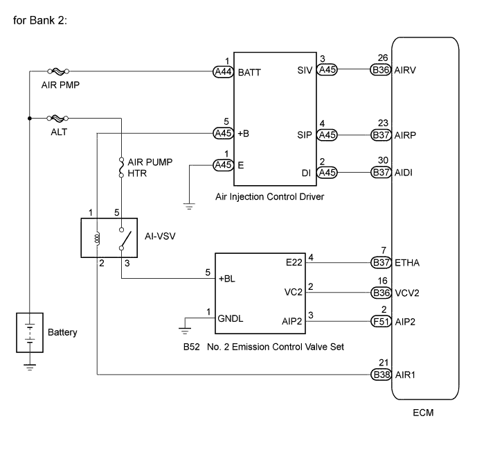
DTC P0416 Secondary Air Injection System Switching Valve "B" Circuit Open |
DTC P0417 Secondary Air Injection System Switching Valve "B" Circuit Shorted |
| DTC No. | DTC Detection Condition | Trouble Area |
| P0416 | Open or short in the air injection VSV relay (AI-VSV) circuit for 3 seconds (1 trip detection logic). |
|
| P0417 | Open or short in the air injection VSV relay (AI-VSV) circuit for 3 seconds (1 trip detection logic). |
|
| Related DTCs | P0416: Secondary air injection system air switching valve circuit range check low voltage (Bank 2) P0417: Secondary air injection system air switching valve circuit range check high voltage (Bank 2) |
| Required Sensors/Components | Air injection VSV relay (AI-VSV) |
| Required Sensors/Components | ECM |
| Frequency of Operation | Continuous |
| Duration | 3 seconds |
| MIL Operation | Immediate |
| Sequence of Operation | None |
| Monitor runs whenever following DTCs not stored | None |
| Current air injection VSV relay (AI-VSV) state | OFF |
| Last air injection VSV relay (AI-VSV) state | OFF |
| Battery voltage | 8 V or higher |
| Ignition switch | ON |
| Starter | OFF |
| Monitor runs whenever following DTCs not stored | None |
| Current air injection VSV relay (AI-VSV) state | ON |
| Last air injection VSV relay (AI-VSV) state | ON |
| Battery voltage | 8 V or higher |
| Ignition switch | ON |
| Starter | OFF |
| Air injection VSV relay (AI-VSV) output terminal voltage | Low |
| Air injection VSV relay (AI-VSV) output terminal voltage | High |
| Techstream Display | Description |
| NORMAL |
|
| ABNORMAL |
|
| INCOMPLETE |
|
| N/A |
|
| 1.INSPECT AIR INJECTION VSV RELAY (AI-VSV) |
Inspect the air injection VSV relay (AI-VSV) (Click here).
|
| ||||
| OK | |
 |
| 2.CHECK AIR INJECTION VSV RELAY (POWER SOURCE) |
Remove the air injection VSV relay (AI-VSV).
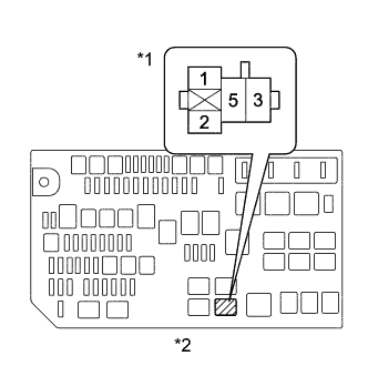 |
Measure the voltage according to the value(s) in the table below.
| Tester Connection | Condition | Specified Condition |
| Air injection VSV relay (AI-VSV) terminal 1 - Body ground | Ignition switch ON | 11 to 14 V |
| Air injection VSV relay (AI-VSV) terminal 5 - Body ground | Always | 11 to 14 V |
| *1 | Air Injection VSV Relay (AI-VSV) |
| *2 | Engine Room Relay Block |
Reinstall the air injection VSV relay (AI-VSV).
|
| ||||
| OK | |
|
| 3.CHECK HARNESS AND CONNECTOR (ECM - AIR INJECTION VSV RELAY) |
Remove the air injection VSV relay (AI-VSV).
Disconnect the ECM connector.
Measure the resistance according to the value(s) in the table below.
| Tester Connection | Condition | Specified Condition |
| Air injection VSV relay (AI-VSV) terminal 2 - B38-21 (AIR1) | Always | Below 1 Ω |
| Air injection VSV relay (AI-VSV) terminal 2 or B38-21 (AIR1) - Body ground | Always | 10 kΩ or higher |
Reinstall the air injection VSV relay (AI-VSV).
Reconnect the ECM connector.
|
| ||||
| OK | ||
 | ||
| ||
| 4.CHECK HARNESS AND CONNECTOR (AIR INJECTION CONTROL DRIVER - AIR INJECTION VSV RELAY) |
Remove the air injection VSV relay (AI-VSV).
Disconnect the air injection control driver connector.
Measure the resistance according to the value(s) in the table below.
| Tester Connection | Condition | Specified Condition |
| Air injection VSV relay (AI-VSV) terminal 1 - A45-5 (+B) | Always | Below 1 Ω |
| Air injection VSV relay (AI-VSV) terminal 1 or A45-5 (+B) - Body ground | Always | 10 kΩ or higher |
Reinstall the air injection VSV relay (AI-VSV).
Reconnect the air injection control driver connector.
|
| ||||
| OK | |
|
| 5.CHECK AIR INJECTION CONTROL DRIVER (POWER SOURCE CIRCUIT) |
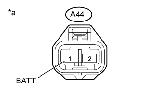 |
Disconnect the air injection control driver connector.
Turn the ignition switch to ON.
Measure the voltage according to the value(s) in the table below.
| Tester Connection | Switch Condition | Specified Condition |
| A44-1 (BATT) - Body ground | Always | 11 to 14 V (near battery voltage) |
| *a | Front view of wire harness connector (to Air Injection Control Driver) |
Reconnect the air injection control driver connector.
|
| ||||
| OK | |
|
| 6.CHECK HARNESS AND CONNECTOR (AIR INJECTION CONTROL DRIVER - ECM, BODY GROUND) |
Disconnect the ECM connector.
Disconnect the air injection control driver connector.
Measure the resistance according to the value(s) in the table below.
| Tester Connection | Condition | Specified Condition |
| B37-23 (AIRP) - A45-4 (SIP) | Always | Below 1 Ω |
| B36-26 (AIRV) - A45-3 (SIV) | Always | Below 1 Ω |
| B37-30 (AIDI) - A45-2 (DI) | Always | Below 1 Ω |
| A45-1 (E) - Body ground | Always | Below 1 Ω |
| B37-23 (AIRP) or A45-4 (SIP) - Body ground | Always | 10 kΩ or higher |
| B36-26 (AIRV) or A45-3 (SIV) - Body ground | Always | 10 kΩ or higher |
| B37-30 (AIDI) or A45-2 (DI) - Body ground | Always | 10 kΩ or higher |
Reconnect the ECM connector.
Reconnect the air injection control driver connector.
|
| ||||
| OK | |
|
| 7.INSPECT AIR INJECTION CONTROL DRIVER (DI TERMINAL) |
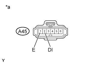 |
Disconnect the air injection control driver connector.
Turn the ignition switch to ON.
Measure the voltage according to the value(s) in the table below.
| Tester Connection | Switch Condition | Specified Condition |
| A45-2 (DI) - A45-1 (E) | Ignition switch ON | 11 to 14 V (near battery voltage) |
| *a | Front view of wire harness connector (to Air Injection Control Driver) |
Reconnect the air injection control driver connector.
|
| ||||
| OK | ||
| ||
| ||

