 |
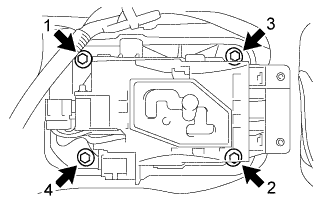
Install and tighten the 4 bolts in the sequence shown in the illustration.
- Torque:
- 18 N*m{ 184 kgf*cm , 13 ft.*lbf }
SHIFT LEVER > INSTALLATION |
| 1. INSTALL SHIFT LEVER ASSEMBLY |
|
Install and tighten the 4 bolts in the sequence shown in the illustration.
Engage the wire harness clamp.
Connect the 2 connectors.
| 2. INSTALL CONSOLE BOX ASSEMBLY |
| 3. CONNECT FLOOR SHIFT GEAR SHIFTING ROD SUB-ASSEMBLY |
While pushing the shift lock release button, move the shift lever to N.
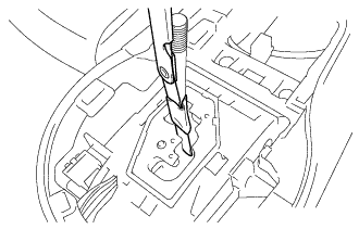 |
Using tape, hold a 0.3 mm feeler gauge on the floor shift control select lever.
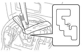 |
Using tape, attach the floor shift control select lever to the console box assembly.
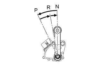 |
Turn the transmission control shaft lever RH of the park/neutral position switch assembly counterclockwise until it stops, and turn it clockwise 2 notches to set it to the N position.
Temporarily install the floor shift gear shifting rod sub-assembly with the nut.
Tighten the nut while lightly pushing the lever rearward.
| 4. INSPECT SHIFT LEVER POSITION |
When moving the shift lever from P to R with the ignition switch to ON and the brake pedal depressed, make sure that it moves smoothly and correctly into position.
Check that the shift lever does not stop when moving the shift lever from R to P, and check that the shift lever does not stick when moving the shift lever from D to M.
Start the engine and make sure that the vehicle moves forward after moving the shift lever from N to D and moves rearward after moving the shift lever to R.
If the operation cannot be performed as specified, inspect the park/neutral position switch assembly and check the shift lock control unit assembly installation condition.
| 5. INSTALL NO. 2 ENGINE UNDER COVER |
Install the 7 bolts and the No. 2 engine under cover.
| 6. INSTALL NO. 1 ENGINE UNDER COVER |
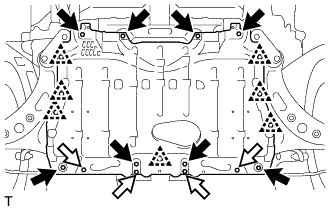 |
Install the No. 1 engine under cover with the 12 bolts and engage the 7 clips.
 | Bolt A |
 | Bolt B |