 |
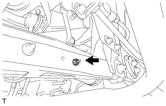
Remove the nut and separate the rear height control sensor sub-assembly LH from the rear No. 2 suspension arm assembly LH.
REAR AXLE CARRIER > REMOVAL |
| 1. REMOVE REAR AXLE HUB AND BEARING ASSEMBLY LH |
| 2. DISASSEMBLY PARKING BRAKE ASSEMBLY |
| 3. SEPARATE REAR HEIGHT CONTROL SENSOR SUB-ASSEMBLY LH (w/ HID Headlight System) |
|
Remove the nut and separate the rear height control sensor sub-assembly LH from the rear No. 2 suspension arm assembly LH.
| 4. SEPARATE STABILIZER LINK SUB-ASSEMBLY (for LH Side) |
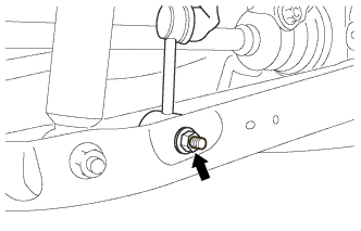 |
Remove the bolt, nut and separate the rear stabilizer link sub-assembly from the rear No. 2 suspension arm assembly LH.
| 5. SEPARATE NO. 3 PARKING BRAKE CABLE ASSEMBLY |
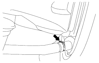 |
Remove the clip and separate the No. 3 parking brake cable assembly from the parking brake plate sub-assembly.
| 6. SEPARATE REAR UPPER CONTROL ARM ASSEMBLY LH |
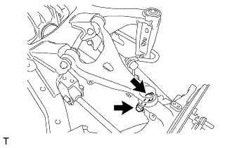 |
Remove the bolt and the nut, and separate the rear upper control arm assembly LH from rear axle carrier.
| 7. SEPARATE REAR NO. 1 SUSPENSION ARM ASSEMBLY LH |
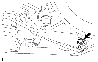 |
Remove the bolt and the nut, and separate the rear No. 1 suspension arm assembly LH from the rear axle carrier.
| 8. SEPARATE REAR NO. 2 SUSPENSION ARM ASSEMBLY LH |
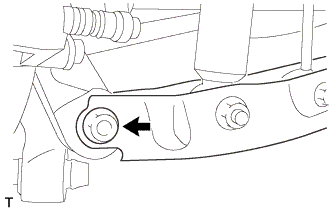 |
Remove the bolt and the nut, and separate the rear No. 2 suspension arm assembly LH from the rear axle carrier.
| 9. DISCONNECT TOE CONTROL LINK SUB-ASSEMBLY LH |
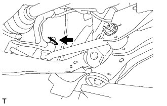 |
Remove the cotter pin.
Remove the nut.
Install the SST (spacer B) as shown in the illustration.
Using SST, disconnect the toe control link sub-assembly LH from the rear axle carrier as shown in the illustration.
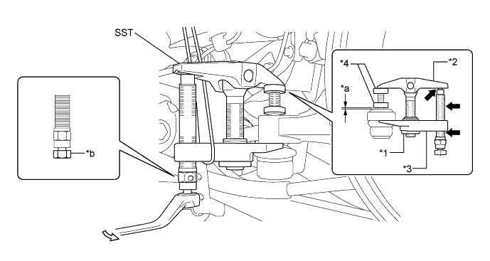
| *1 | Nut | *2 | Body |
| *3 | Claw | *4 | SST (Spacer B) |
| *a | 1 mm (0.0394 in.) | *b | Place a Wrench Here |
 | Molybdenum Grease |  | Turn |
| 10. REMOVE PARKING BRAKE PLATE SUB-ASSEMBLY |
| 11. REMOVE REAR AXLE CARRIER SUB-ASSEMBLY LH |
Hold the drive shaft and remove the rear axle carrier sub-assembly LH.