 |
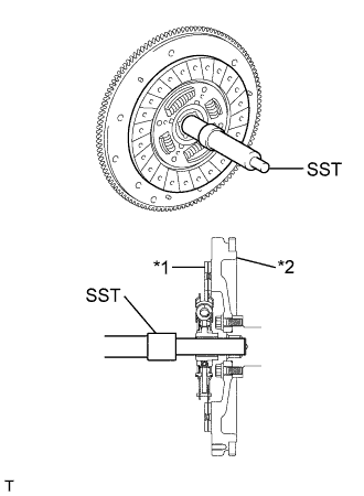
Insert SST into the clutch disc assembly, and then insert them both into the flywheel sub-assembly.
| *1 | Clutch Disc Assembly |
| *2 | Flywheel Sub-assembly |
- SST
- 09301-00110
- NOTICE:
- Insert the clutch disc assembly in the correct direction.
CLUTCH UNIT > INSTALLATION |
| 1. INSTALL CLUTCH DISC ASSEMBLY |
|
Insert SST into the clutch disc assembly, and then insert them both into the flywheel sub-assembly.
| *1 | Clutch Disc Assembly |
| *2 | Flywheel Sub-assembly |
| 2. INSTALL CLUTCH COVER ASSEMBLY |
Reuse the flywheel sub-assembly and clutch cover assembly:
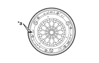 |
Align the matchmark on the clutch cover assembly with that on the flywheel sub-assembly.
| *a | Matchmark |
Replace the flywheel sub-assembly or clutch cover assembly:
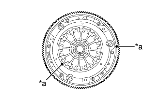 |
Position the clutch cover assembly so that there is a gap of at least 120° between the unbalance marks on the flywheel sub-assembly and the clutch cover assembly.
| *a | Unbalance Mark |
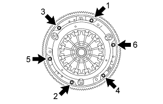 |
Following the procedures shown in the illustration, tighten the 6 bolts in order, starting with the bolt located near the knock pin at the top.
| 3. INSPECT AND ADJUST CLUTCH COVER ASSEMBLY |
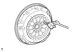 |
Using a dial indicator with a roller instrument, measure the diaphragm spring tip alignment.
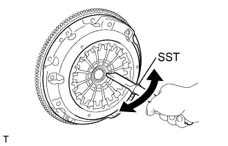 |
If the alignment is not as specified, using SST, adjust the diaphragm spring tip alignment.
| 4. INSTALL RELEASE FORK SUPPORT |
Install the release fork support to the manual transmission assembly.
| 5. INSTALL CLUTCH RELEASE FORK BOOT |
Install the clutch release fork boot to the manual transmission assembly.
| 6. INSTALL RELEASE BEARING HUB CLIP |
Install the 3 release bearing hub clips to the clutch release bearing assembly.
Install the release bearing hub clip to the clutch release fork sub-assembly.
| 7. INSTALL CLUTCH RELEASE FORK SUB-ASSEMBLY |
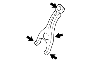 |
Apply release hub grease to the contact surfaces of the clutch release fork sub-assembly and clutch release bearing assembly, clutch release fork sub-assembly and clutch release cylinder push rod, and clutch release fork sub-assembly and release fork support.
 | Release Hub Grease |
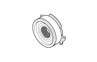 |
Apply release hub grease to the clutch release bearing assembly as shown in the illustration.
 | Release Hub Grease |
Engage the 2 release bearing hub clips and install the clutch release fork sub-assembly to the clutch release bearing assembly.
| 8. INSTALL CLUTCH RELEASE BEARING ASSEMBLY |
Install the clutch release bearing assembly with the clutch release fork sub-assembly to the manual transmission assembly.
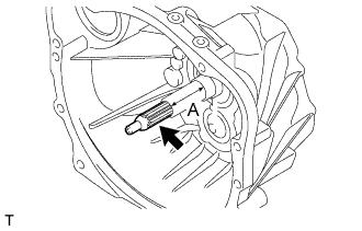 |
Apply clutch spline grease to the input shaft spline.
| Clutch Spline Grease |
| 9. INSTALL MANUAL TRANSMISSION ASSEMBLY |