MANUAL TRANSMISSION ASSEMBLY > INSTALLATION |
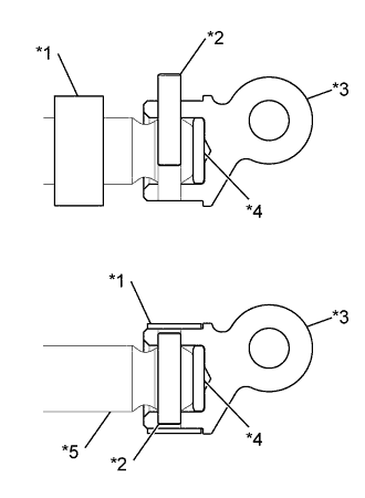
| 1. INSTALL CONTROL SHAFT |
|
Install a new control shaft collar onto the shift shaft.
Install the shift lever damper and control shaft to the shift shaft.
Using a pin punch (5 mm (0.197 in.)) and a hammer, align the control shaft hole and the shift shaft hole with the cutout of the control shaft collar, and insert the shaft pin from above.
Slide the control shaft collar until it comes into contact with the stopper of the control shaft, then stake it to the cutout.
| *1 | Control Shaft Collar |
| *2 | Shaft Pin |
| *3 | Control Shaft |
| *4 | Shift Lever Damper |
| *5 | Shift Shaft |
| 2. INSTALL FLOOR SHIFT CONTROL SHAFT |
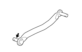 |
Apply a light coat of MP grease to the floor shift control shaft.
 | MP grease |
Install the floor shift control shaft and 2 collars to the control shaft.
Install the plate washer and clip.
| 3. INSTALL REAR NO. 1 ENGINE MOUNTING INSULATOR |
Install the rear No. 1 engine mounting insulator to the manual transmission assembly with the 4 bolts.
| 4. INSTALL MANUAL TRANSMISSION ASSEMBLY |
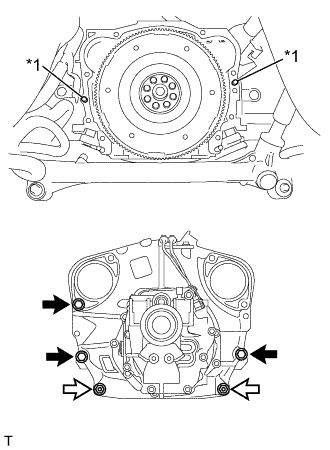 |
Confirm that 2 knock pins are on the manual transmission assembly contact surface of the engine cylinder block before manual transmission assembly installation.
Install the manual transmission assembly to the engine with the 3 bolts and 2 nuts.
| *1 | Knock Pin |
| Bolt |
 | Nut |
| 5. INSTALL FLOOR SHIFT CONTROL SHIFT LEVER RETAINER |
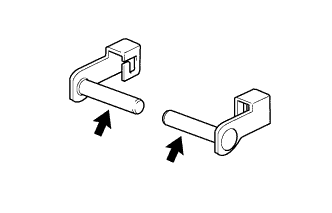 |
Apply a light coat of MP grease to new 2 shift lever pins.
| MP grease |
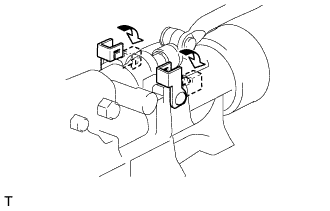 |
Install the floor shift control shift lever retainer with the 2 shift lever pins.
Secure the shift lever pins to the extension housing sub-assembly.
| 6. INSTALL REAR NO. 2 ENGINE MOUNTING INSULATOR |
Tilt up the manual transmission assembly.
Install the rear No. 2 engine mounting insulator to the rear No. 1 engine mounting insulator with 2 washers and 2 nuts.
Install the rear No. 2 engine mounting insulator to the body with the 4 bolts.
| 7. INSTALL EXHAUST PIPE BRACKET |
Install the exhaust pipe bracket with the 2 bolts.
| 8. INSTALL SHIFT AND SELECT LEVER BOOT |
Temporarily install a new shift and select lever boot to the floor shift lever assembly.
| 9. INSTALL FLOOR SHIFT LEVER ASSEMBLY |
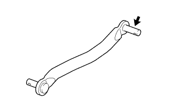 |
Apply a light coat of MP grease to the floor shift control shaft.
| MP grease |
Install the O-ring and 2 bushings to the shift lever assembly.
Install the plate washer to the floor shift lever assembly.
Install the shift lever assembly with the clip.
Install the shift and select lever boot.
| 10. INSTALL EXHAUST MANIFOLD |
| 11. INSTALL MANUAL TRANSMISSION ASSEMBLY |
Install the bolt to the manual transmission assembly.
| 12. INSTALL CLUTCH RELEASE CYLINDER ASSEMBLY |
Install the clutch release cylinder assembly with the 2 bolts.
| 13. CONNECT WIRE HARNESS |
Install the wire harness clamp bracket with the bolt.
Engage the wire harness clamp.
Connect the ground cable with the bolt.
Connect the 2 connectors.
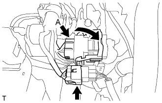 |
Connect the 2 connectors.
| 14. INSTALL STARTER ASSEMBLY |
| 15. INSTALL FRONT STABILIZER BAR |
| 16. INSTALL PROPELLER SHAFT WITH CENTER BEARING ASSEMBLY |
| 17. CONNECT CABLE TO NEGATIVE BATTERY TERMINAL |
| 18. ADD MANUAL TRANSMISSION OIL |
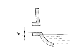 |
Add manual transmission oil until the oil level is within 5 mm (0.197 in.) from the bottom of the manual transmission filler plug opening.
| *a | 0 to 5 mm (0 to 0.197 in.) |
Check for oil leakage when the oil level is low.
Install the transmission filler plug and a new gasket.
| 19. INSPECT MANUAL TRANSMISSION OIL |
Stop the vehicle in a level place.
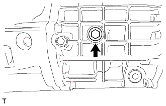 |
Remove the manual transmission filler plug and the gasket.
|
Check that the oil surface is within 5 mm (0.197 in.) of the bottom of the manual transmission filler plug opening.
| *a | 0 to 5 mm (0 to 0.197 in.) |
Check for oil leakage when the oil level is low.
Install the manual transmission filler plug and a new gasket.
| 20. INSPECT FOR MANUAL TRANSMISSION OIL LEAK |
| 21. INSTALL REAR ENGINE UNDER COVER LH (w/ Floor Under Cover) |
Install the rear engine under cover LH with the 3 bolts and 8 clips.
| 22. INSTALL REAR ENGINE UNDER COVER RH (w/ Floor Under Cover) |
| 23. INSTALL NO. 2 ENGINE UNDER COVER |
Install the 7 bolts and the No. 2 engine under cover.
| 24. INSTALL NO. 1 ENGINE UNDER COVER |
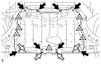 |
Install the No. 1 engine under cover with the 12 bolts and engage the 7 clips.
| Bolt A |
| Bolt B |