 |
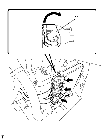
Connect the 4 connectors to the injector driver. Move the lock levers in the direction indicated by the arrow to lock the 3 connectors.
| *1 | Lock Lever |
 | Lock with Connector |
 | Normal Connector |
FUEL INJECTOR (for Port Injection) > INSTALLATION |
| 1. INSTALL FUEL INJECTOR ASSEMBLY |
Apply gasoline to a new fuel injector O-ring and a new fuel injector grommet, and then install them to the injector.
Install the 4 fuel injector assemblies to the fuel delivery pipe.
| 2. INSTALL FUEL INJECTOR SEAL (for Bank 1) |
Install 2 new fuel injector seals.
| 3. INSTALL FUEL INJECTOR SEAL |
| 4. INSTALL FUEL INJECTOR SEAL (for Bank 2) |
Install 2 new fuel injector seals.
| 5. INSTALL FUEL DELIVERY PIPE (for Bank 1) |
Install the fuel delivery pipe (with injector) to the intake manifold with the 2 bolts.
Engage the clamp to connect the wire harness.
Connect the 2 fuel injector assembly connectors.
Connect the fuel delivery tube to the fuel delivery pipe (Click here).
| 6. INSTALL FUEL DELIVERY PIPE (for Bank 2) |
Install the fuel delivery pipe (with injector) to the intake manifold with the 2 bolts.
Connect the 2 injector connectors and clamp.
Connect the fuel delivery tube to the fuel delivery pipe (Click here).
| 7. INSTALL FUEL DELIVERY PIPE SUB-ASSEMBLY (for Clamp Type) |
Connect the No. 2 fuel vapor feed hose to the fuel delivery pipe sub-assembly.
Install the fuel delivery pipe sub-assembly to the intake manifold with the bolt.
| 8. CONNECT NO. 1 FUEL HOSE (for Clamp Type) |
Connect the No. 1 fuel hose to the fuel delivery pipe with the clamp.
Tighten the hose clamp bolt.
| 9. INSTALL INJECTOR COVER (for Bank 2) |
for Resin Intake Manifold:
Install the injector cover (for bank 2) to the intake manifold with the 2 bolts.
for Aluminum Intake Manifold:
Engage the 2 guides and install the injector cover to the intake manifold with the 2 bolts.
Install the wire harness clamp bracket to the injector cover (for bank 2) with the bolt.
| 10. CONNECT NO. 2 FUEL HOSE (for Metal Type) |
Connect the No. 2 fuel hose to the fuel delivery pipe sub-assembly with the clamp.
| 11. CONNECT NO. 3 FUEL HOSE (for Metal Type) |
Connect the No. 3 fuel hose to the fuel delivery pipe sub-assembly (Click here).
| 12. CONNECT NO. 1 FUEL HOSE (for Metal Type) |
Connect the No. 1 fuel hose to the fuel delivery pipe (Click here).
| 13. INSTALL INJECTOR COVER (for Bank 1) |
for Resin Intake Manifold:
Install the injector cover (for bank 1) to the intake manifold with the 2 bolts.
for Aluminum Intake Manifold:
Engage the 2 guides and install the injector cover to the intake manifold with the 2 bolts.
Engage the 4 clamps to install the wire harness to the injector cover (for bank 1).
| 14. INSTALL INJECTOR DRIVER |
Install the injector driver with the 3 bolts.
|
Connect the 4 connectors to the injector driver. Move the lock levers in the direction indicated by the arrow to lock the 3 connectors.
| *1 | Lock Lever |
| Lock with Connector |
| Normal Connector |
| 15. INSTALL CHAMBER ASSEMBLY |
| 16. CONNECT CABLE TO NEGATIVE BATTERY TERMINAL |
| 17. INSPECT FOR FUEL LEAK |
Connect the GTS to the DLC3.
Turn the ignition switch to ON.
Turn the GTS on.
Enter the following menus: Power train / Engine / Active Test / Control the Fuel Pump / Speed.
Check the fuel pump operation.
Check for pressure in the fuel inlet tube from the fuel line. Check that sound of fuel flowing in the fuel tank can be heard.
If no sound can be heard, check the EFI MAIN 1 relay, fuel pump, ECM and wiring connector.
Inspect for fuel leaks.
Check that there are no fuel leaks anywhere on the system after performing maintenance.
If there is a fuel leak, repair or replace parts as necessary.