 |
Remove the bolt.
FUEL TANK > REMOVAL |
| 1. DISCHARGE FUEL SYSTEM PRESSURE |
| 2. DISCONNECT CABLE FROM NEGATIVE BATTERY TERMINAL |
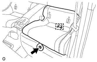
| 3. REMOVE SEPARATE TYPE REAR SEAT CUSHION ASSEMBLY LH |
|
Remove the bolt.
Disengage the hook and remove the separate type rear seat cushion assembly LH.
| 4. REMOVE SEPARATE TYPE REAR SEAT CUSHION ASSEMBLY RH |
| 5. REMOVE NO. 2 REAR FLOOR SERVICE HOLE COVER |
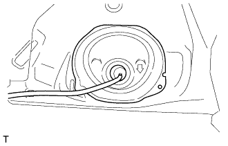 |
Remove the No. 2 rear floor service hole cover.
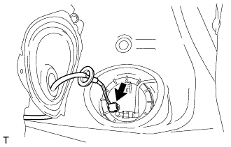 |
Disconnect the fuel suction tube assembly with pump and gauge connector.
| 6. REMOVE REAR FLOOR SERVICE HOLE COVER |
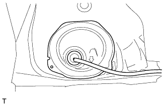 |
Remove the rear floor service hole cover.
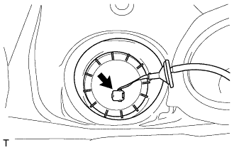 |
Disconnect the fuel tank return tube connector.
| 7. REMOVE FUEL SUCTION TUBE ASSEMBLY WITH PUMP AND GAUGE |
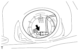 |
Disconnect the fuel tank main tube (Click here).
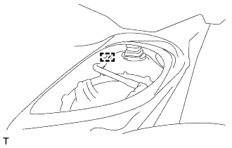 |
Disengage the clamp and separate the fuel tank main tube from the fuel tank assembly.
Remove the fuel pump gauge retainer.
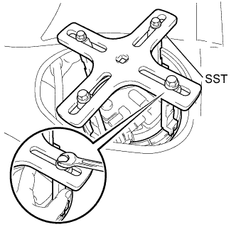 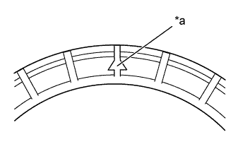 |
Temporarily install SST to the fuel pump gauge retainer.
| *a | Marked Part |
While securely pressing SST (claws) against the fuel pump gauge retainer ribs, tighten the 4 bolts.
Install SST (handle).
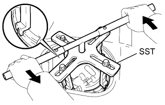 |
Lightly press down on SST to prevent it from separating from the fuel pump gauge retainer. While pressing SST, rotate the handle slowly to loosen the fuel pump gauge retainer.
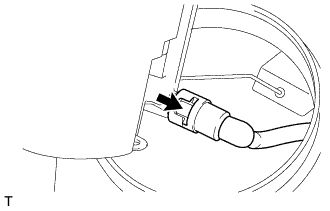 |
Disconnect the fuel tank vent hose sub-assembly (Click here).
Remove the fuel suction tube assembly with pump and gauge from the fuel tank assembly.
Remove the gasket from the fuel tank assembly.
| 8. REMOVE FUEL TANK RETURN TUBE |
|
Temporarily install SST to the fuel pump gauge retainer.
| *a | Marked Part |
While securely pressing SST (claws) against the fuel pump gauge retainer ribs, tighten the 4 bolts.
Install SST (handle).
|
Lightly press down on SST to prevent it from separating from the fuel pump gauge retainer. While pressing SST, rotate the handle slowly to loosen the fuel pump gauge retainer.
Remove the fuel pump gauge retainer.
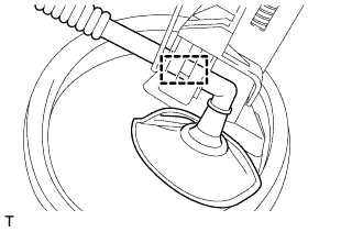 |
Disengage the clamp and separate the fuel tank vent hose sub-assembly from the fuel tank return tube.
Remove the fuel tank return tube from the fuel tank assembly.
Remove the gasket from the fuel tank assembly.
| 9. DRAIN FUEL |
| 10. REMOVE REAR SUSPENSION MEMBER SUB-ASSEMBLY |
| 11. REMOVE NO. 3 FUEL TANK PROTECTOR (for Metal Type) |
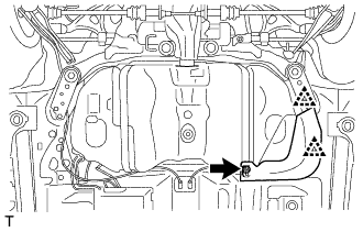 |
Remove the nut, 2 clips and No. 3 fuel tank protector.
| 12. REMOVE NO. 1 FUEL TANK PROTECTOR (for Clamp Type) |
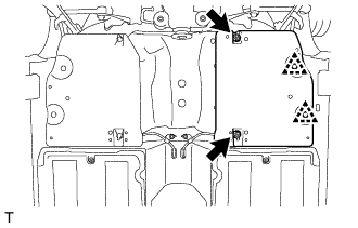 |
Remove the 2 nuts, 2 clip and No. 1 fuel tank protector.
| 13. REMOVE NO. 2 FUEL TANK PROTECTOR (for Clamp Type) |
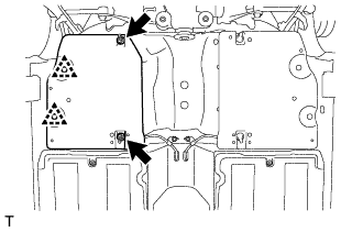 |
Remove the 2 nuts, 2 clips and No. 2 fuel tank protector.
| 14. REMOVE NO. 3 PARKING BRAKE CABLE ASSEMBLY |
Remove the 4 bolts and separate the No. 3 parking brake cable assembly from the vehicle.
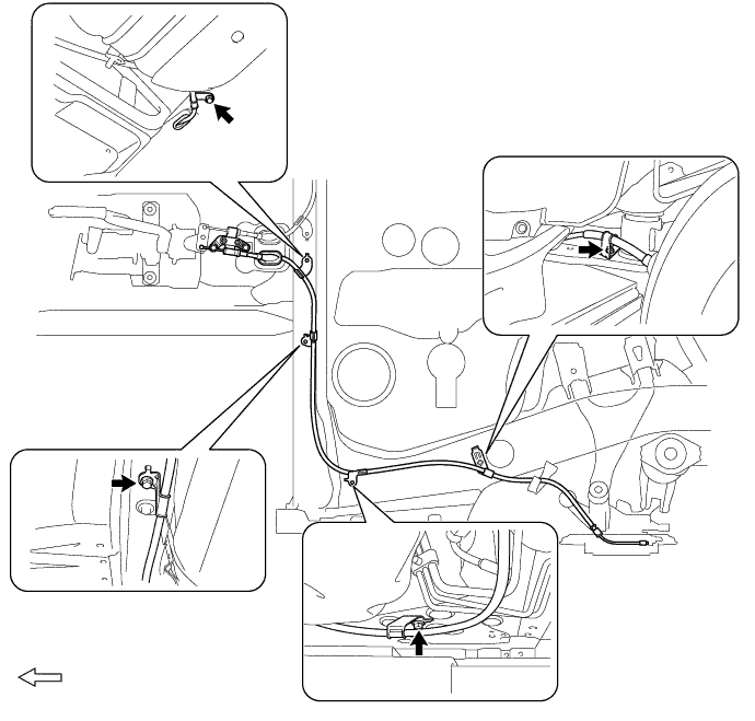
 | Bolt |  | Vehicle Front Side |
 |
Remove the clamp and remove the No. 3 parking brake cable assembly.
| 15. REMOVE NO. 2 PARKING BRAKE CABLE ASSEMBLY |
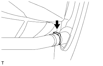
| 16. DISCONNECT FUEL TANK TO FILLER PIPE HOSE (for Metal Type) |
 |
Loosen the hose clamp bolt and disconnect the fuel tank to filler pipe hose.
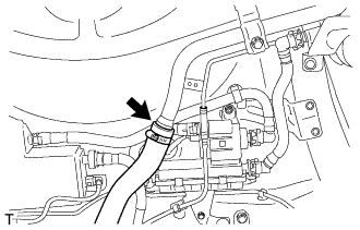
| 17. DISCONNECT FUEL TANK VENT HOSE SUB-ASSEMBLY (for Metal Type) |
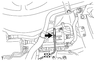 |
Remove the clamp and disconnect the fuel tank vent hose sub-assembly.
Disengage the clamp and separate the tube.
| 18. SEPARATE CHARCOAL CANISTER ASSEMBLY (for Metal Type) |
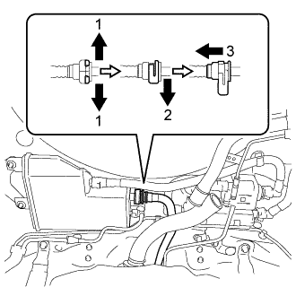 |
Disconnect the quick connector as indicated by the arrows in the order shown in the illustration.
| 19. DISCONNECT FUEL TANK TO FILLER PIPE HOSE (for Clamp Type) |
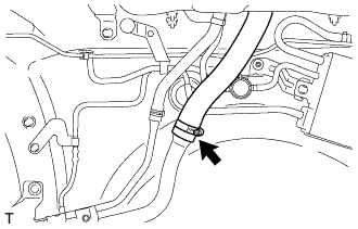 |
Loosen the hose clamp bolt and disconnect the fuel tank to filler pipe hose.
| 20. DISCONNECT FUEL TANK VENT HOSE SUB-ASSEMBLY (for Clamp Type) |
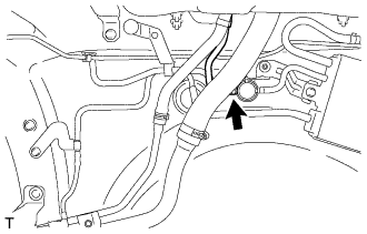 |
Disconnect the fuel tank vent hose sub-assembly.
| 21. DISCONNECT NO. 6 FUEL TANK BREATHER TUBE (for Clamp Type) |
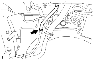 |
Remove the clamp and disconnect the No. 6 fuel tank breather tube.
| 22. REMOVE FUEL TANK ASSEMBLY |
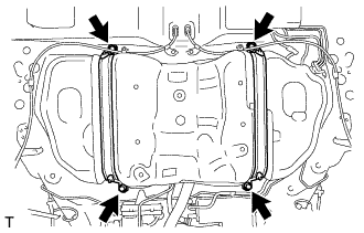 |
Place an engine lifter under the fuel tank assembly.
Remove the 4 bolts, 2 No. 1 fuel tank bands and fuel tank assembly.
| 23. REMOVE FUEL TANK TO FILLER PIPE HOSE (for Metal Type) |
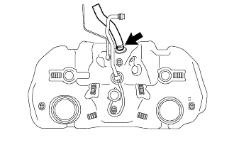 |
Loosen the hose clamp bolt and remove the fuel tank to filler pipe hose from the fuel tank.
| 24. REMOVE FUEL TANK TO FILLER PIPE HOSE (for Clamp Type) |
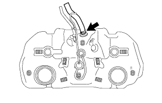 |
Loosen the hose clamp bolt and remove the fuel tank to filler pipe hose from the fuel tank.
| 25. REMOVE NO. 2 FUEL TANK MAIN TUBE SUB-ASSEMBLY (for Metal Type) |
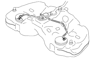 |
Remove the No. 2 fuel tank main tube sub-assembly from the fuel tank assembly.
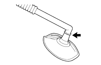 |
Remove the fuel filter from the No. 2 fuel tank main tube sub-assembly.
| 26. REMOVE NO. 2 FUEL TANK MAIN TUBE SUB-ASSEMBLY (for Clamp Type) |
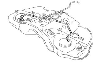 |
Remove the No. 2 fuel tank main tube sub-assembly from the fuel tank assembly.
|
Remove the fuel filter from the No. 2 fuel tank main tube sub-assembly.
| 27. REMOVE NO. 1 FUEL TANK CUSHION (for Metal Type) |
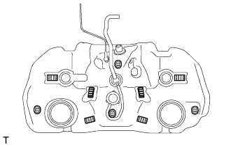 |
Remove the 10 No. 1 fuel tank cushions shown in the illustration.
| 28. REMOVE NO. 1 FUEL TANK CUSHION (for Clamp Type) |
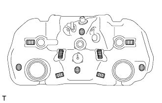 |
Remove the 10 No. 1 fuel tank cushions shown in the illustration.