 |
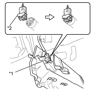
Connect the airbag connector to the lower No. 1 instrument panel airbag assembly.
| *1 | Airbag Connector |
| *2 | Airbag Connector Lock |
- NOTICE:
- When connecting any airbag connector, take care not to damage the airbag wire harness.
KNEE AIRBAG ASSEMBLY > INSTALLATION |
| 1. INSTALL LOWER NO. 1 INSTRUMENT PANEL AIRBAG ASSEMBLY |
Check that the ignition switch is off.
Check that the cable is disconnected from the negative (-) battery terminal.
|
Connect the airbag connector to the lower No. 1 instrument panel airbag assembly.
| *1 | Airbag Connector |
| *2 | Airbag Connector Lock |
Push in the lock to install the airbag connector.
Install the lower No. 1 instrument panel airbag assembly with the 2 nuts.
| 2. INSTALL NO. 2 INSTRUMENT PANEL UNDER COVER SUB-ASSEMBLY |
for LHD
Engage the 3 claws and 4 clips and install the No. 2 instrument panel under cover sub-assembly.
for RHD
Engage the 3 claws and 4 clips.
Connect the cooler thermistor hose and connector and install the No. 2 instrument panel under cover sub-assembly.
| 3. INSTALL NO. 1 INSTRUMENT PANEL UNDER COVER SUB-ASSEMBLY |
Connect each connector.
Engage the 2 claws.
Engage the 6 clips to install the No. 1 instrument panel under cover sub-assembly.
Install the screw.
| 4. INSTALL INSTRUMENT SIDE PANEL |
| 5. CONNECT CABLE TO NEGATIVE BATTERY TERMINAL |
| 6. PERFORM DIAGNOSTIC SYSTEM CHECK |
| 7. INSPECT SRS WARNING LIGHT |