 |
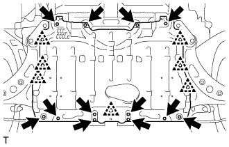
Disengage the 7 clips and remove the 12 bolts and No. 1 engine under cover.
STEERING COLUMN ASSEMBLY > REMOVAL |
| 1. PRECAUTION |
| 2. TURN FRONT WHEELS TO FACE STRAIGHT AHEAD |
| 3. REMOVE NO. 1 ENGINE UNDER COVER |
|
Disengage the 7 clips and remove the 12 bolts and No. 1 engine under cover.
| 4. REMOVE NO. 2 ENGINE UNDER COVER |
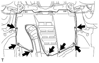 |
Remove the 7 bolts and the No. 2 engine under cover.
| 5. REMOVE STEERING WHEEL ASSEMBLY |
| 6. REMOVE INSTRUMENT SIDE PANEL (w/o Knee Airbag) |
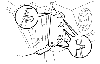 |
Using a moulding remover, disengage the claw and 4 clips and remove the instrument side panel.
| *1 | Moulding Remover |
| 7. REMOVE NO. 1 INSTRUMENT PANEL UNDER COVER SUB-ASSEMBLY (w/o Knee Airbag) |
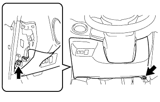 |
Remove the 2 screws.
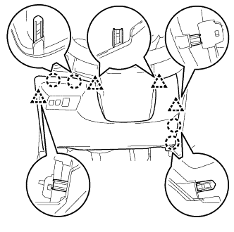 |
Disengage the 4 clips.
Disengage the 4 claws and separate the No. 1 instrument panel under cover sub-assembly.
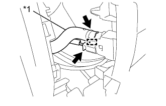 |
w/ Automatic Air Conditioning System for RHD:
Disengage the guide and disconnect the aspirator hose.
Disconnect the connector.
Disconnect each connector and remove the No. 1 instrument panel under cover sub-assembly.
| *1 | Aspirator Hose |
| 8. REMOVE LOWER NO. 1 INSTRUMENT PANEL AIRBAG ASSEMBLY (w/ Knee Airbag) |
| 9. REMOVE CENTER INSTRUMENT CLUSTER FINISH PANEL SUB-ASSEMBLY |
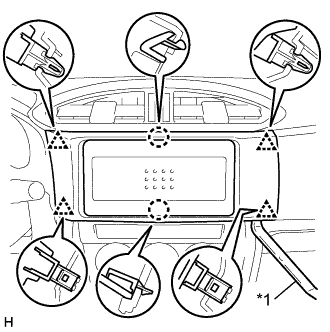 |
Using a moulding remover, disengage the 2 claws and 4 clips to remove the center instrument cluster finish panel sub-assembly.
| *1 | Moulding Remover |
| 10. REMOVE METER HOOD SUB-ASSEMBLY |
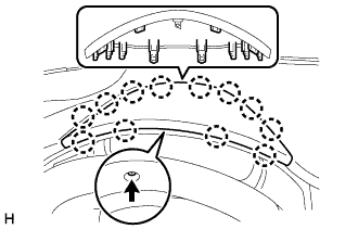 |
Remove the screw.
Disengage the 12 claws, and then pull out the meter hood sub-assembly diagonally upwards to remove it.
| 11. REMOVE UPPER INSTRUMENT PANEL METER ORNAMENT |
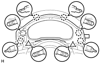 |
Remove the screw.
Disengage the 6 claws and 2 clips.
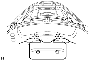 |
Disengage the 2 claws that are holding the upper instrument panel meter ornament and steering column cover together.
Disconnect the connector and remove the upper instrument panel meter ornament.
| 12. REMOVE STEERING COLUMN COVER SUPPORT (w/ Entry and Start System) |
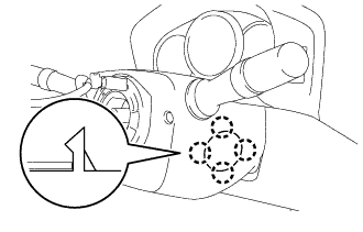 |
Disengage the 4 claws and remove the steering column cover support.
| 13. REMOVE LOWER STEERING COLUMN COVER |
w/ Knee Airbag
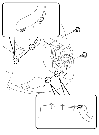 |
Remove the 2 screws.
Disengage the 4 claws and remove the lower steering column cover.
w/o Knee Airbag
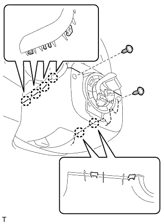 |
Remove the 2 screws.
Disengage the 6 claws and remove the lower steering column cover.
| 14. REMOVE UPPER STEERING COLUMN COVER |
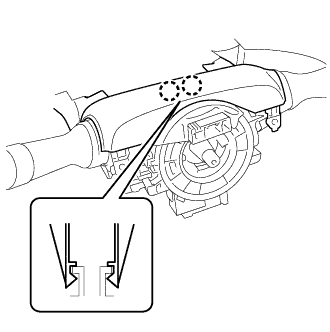 |
Disengage the 2 claws to remove the upper steering column cover.
| 15. REMOVE TURN SIGNAL SWITCH ASSEMBLY WITH SPIRAL CABLE SUB-ASSEMBLY |
Disconnect the each connector from the turn signal switch assembly with spiral cable sub-assembly.
Using pliers, loosen the clamp.
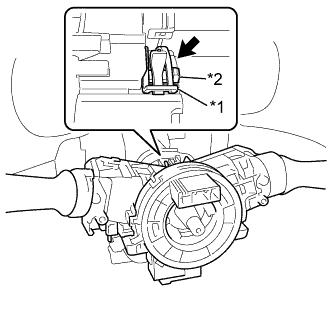 |
With the clamp loosened, use a screwdriver to disengage the claw, and remove the turn signal switch assembly with spiral cable sub-assembly from the steering column assembly.
| *1 | Clamp |
| *2 | Claw |
| 16. REMOVE STEERING INTERMEDIATE SHAFT ASSEMBLY |
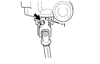 |
Put matchmarks on the steering intermediate shaft assembly and the steering column assembly.
| *1 | Matchmark |
Remove the bolt and separate the steering intermediate shaft assembly from the steering column assembly.
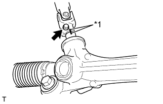 |
Put matchmarks on the steering intermediate shaft assembly and the rack and pinion power steering gear assembly.
| *1 | Matchmark |
Remove the bolt and separate the steering intermediate shaft assembly from the rack and pinion power steering gear assembly.
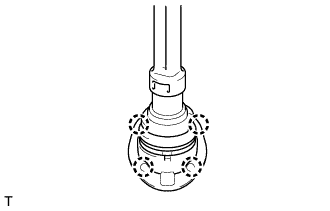 |
Disengage the 4 claws remove the steering intermediate shaft assembly from the exterior of the vehicle cabin.
| 17. REMOVE STEERING COLUMN ASSEMBLY |
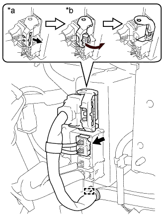 |
Disconnect the 2 connectors from the power steering ECU assembly.
As shown illustration, pull out the lock of the lock lever and turn the lock lever to disconnect the connector.
| *a | Pull out the lock |
| *b | Turn the lock lever |
Disengage the clamp.
Disconnect the each connector and disengage the wire harness clamps from the steering column assembly.
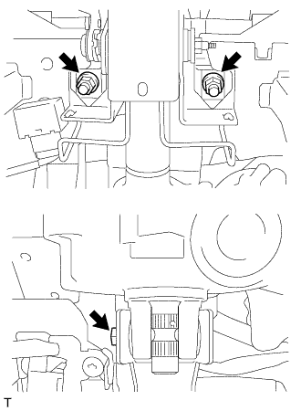 |
Remove the bolt and 2 nuts to remove the steering column assembly.