 |
Fill the clutch fluid.
- Fluid:
- SAE J1703 or FMVSS No. 116 DOT3
- NOTICE:
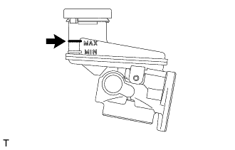
- Add clutch fluid to keep the level between the MIN and MAX lines of the master cylinder reservoir sub-assembly while bleeding the clutch.
CLUTCH MASTER CYLINDER (for LHD) > INSTALLATION |
| 1. INSTALL CLUTCH MASTER CYLINDER TO FLEXIBLE HOSE TUBE |
Install the master cylinder to release cylinder hose to the clutch flexible hose bracket with the clip.
Using a union nut wrench (10 mm), connect the clutch master cylinder to flexible hose tube to the master cylinder to release cylinder hose.
Using a union nut wrench (10 mm), connect the clutch master cylinder to flexible hose tube to the clutch master cylinder assembly.
| 2. INSTALL CLUTCH MASTER CYLINDER ASSEMBLY |
Install the sheet to the clutch master cylinder assembly.
Install the clutch master cylinder assembly with the 2 nuts.
Install the master cylinder to release cylinder hose with a union bolt and 2 new gaskets.
| 3. INSTALL CLUTCH MASTER CYLINDER PUSH ROD CLEVIS |
Apply MP grease to the new clevis pin.
Install the clutch master cylinder push rod clevis to the clutch pedal lever sub-assembly with the clevis pin and a clip.
| 4. FILL UP FILL CLUTCH FLUID |
|
Fill the clutch fluid.
| 5. BLEED CLUTCH LINE |
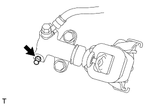 |
Connect a vinyl tube to the clutch release cylinder bleeder plug.
Depress the clutch pedal 5 times, and then loosen the clutch release cylinder bleeder plug while the pedal is depressed (Step C).
When fluid no longer comes out, tighten the clutch release cylinder bleeder plug, and then release the clutch pedal (Step D).
Repeat Steps C and D until all the air in the fluid is completely bled out.
Tighten the clutch release cylinder bleeder plug.
Depress the clutch pedal 10 times or more and confirm its operation.
| 6. INSPECT FOR CLUTCH FLUID LEAK |
| 7. INSPECT CLUTCH FLUID LEVEL |
|
Check the clutch fluid level.
If clutch fluid level is lower than the MIN line, check for leaks and inspect the clutch lines. If necessary, refill the master cylinder reservoir sub-assembly with clutch fluid to the MAX line after repair or replacement.
| 8. INSPECT AND ADJUST CLUTCH PEDAL |
| 9. INSTALL FRONT SUSPENSION UPPER TO COWL BRACE SUB-ASSEMBLY LH |
| 10. INSTALL LOWER NO. 1 INSTRUMENT PANEL AIRBAG ASSEMBLY (w/ Knee Airbag) |
| 11. INSTALL NO. 1 INSTRUMENT PANEL UNDER COVER SUB-ASSEMBLY (w/o Knee Airbag) |
Connect each connector.
 |
for Automatic Air Conditioning System for RHD:
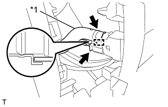
Connect the connector.
Engage the guide and connect the aspirator hose.
| *1 | Aspirator Hose |
Engage the 4 claws.
Engage the 4 clips to install the No. 1 instrument panel under cover sub-assembly.
Install the 2 screws.
| 12. INSTALL INSTRUMENT SIDE PANEL LH (w/o Knee Airbag) |