 |
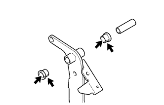
Apply MP grease to the 2 clutch pedal bushes.
 | MP grease |
CLUTCH PEDAL (for RHD) > INSTALLATION |
| 1. INSTALL CLUTCH PEDAL PAD |
Install the clutch pedal pad to the clutch pedal sub-assembly.
| 2. INSTALL NO. 2 CLUTCH PEDAL CUSHION |
Install the No. 2 clutch pedal cushion to the clutch pedal sub-assembly.
| 3. INSTALL NO. 1 CLUTCH PEDAL CUSHION |
Install the 2 No. 1 clutch pedal cushions to the clutch pedal sub-assembly.
| 4. INSTALL BUSH |
Install the 3 bushes to the clutch pedal support sub-assembly and the clutch pedal sub-assembly.
| 5. INSTALL CLUTCH PEDAL SHAFT COLLAR |
|
Apply MP grease to the 2 clutch pedal bushes.
| MP grease |
Install the 2 clutch pedal bushes and the clutch pedal shaft collar to the clutch pedal sub-assembly.
| 6. INSTALL CLUTCH PEDAL SUB-ASSEMBLY |
Install the clutch pedal sub-assembly to the clutch pedal support sub-assembly with the bolt and the nut.
| 7. INSTALL CLUTCH PEDAL SPRING |
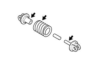 |
Apply MP grease to assist rod A, assist rod B and clutch pedal spring.
| MP grease |
Install the assist rod A, assist rod B, clutch pedal spring and assist bush to the clutch pedal sub-assembly and the clutch pedal support sub-assembly.
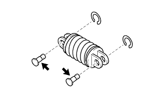 |
Apply MP grease to 2 clevis pins.
| MP grease |
Install the 2 E-ring and the 2 clevis pins.
| 8. INSTALL CLUTCH SWITCH ASSEMBLY |
Install the clutch switch assembly to the clutch pedal support sub-assembly with the nut.
| 9. INSTALL CLUTCH START SWITCH ASSEMBLY |
Install the clutch start switch assembly to the clutch pedal support sub-assembly with the nut.
Connect the clamp.
| 10. INSTALL CLUTCH PEDAL SUPPORT SUB-ASSEMBLY |
Install the clutch pedal support sub-assembly to the vehicle with the bolt.
Apply MP grease to the new clevis pin.
Install the clutch master cylinder push rod clevis to the clutch pedal sub-assembly with the clevis pin and a clip.
Connect the 2 connectors.
| 11. INSPECT AND ADJUST CLUTCH PEDAL |
| 12. INSPECT CLUTCH SWITCH ASSEMBLY |
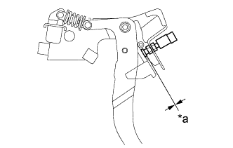 |
Without depressing the clutch pedal, check that there is no clearance between the switch shaft and the clutch pedal stopper.
| *a | No Clearance |
| 13. INSTALL LOWER NO. 1 INSTRUMENT PANEL AIRBAG ASSEMBLY (w/ Knee Airbag) |
| 14. CONNECT CABLE TO NEGATIVE BATTERY TERMINAL |
| 15. INSPECT CLUTCH START SYSTEM |
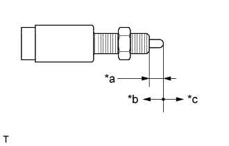 |
Measure the resistance according to the value(s) in the table below.
| *a | 5.0 to 6.5 mm (0.197 to 0.256 in.) |
| *b | ON |
| *c | OFF |
| Tester Connection | Switch Condition | Specified Condition |
| 1 - 2 | ON (Pushed in) | Below 1Ω |
| OFF (Released) | 10 kΩ or higher |