Home › Vehicle Interior › HEATING / AIR CONDITIONING › FRONT EVAPORATOR TEMPERATURE SENSOR

FRONT EVAPORATOR TEMPERATURE SENSOR > INSTALLATION

for Preparation Click here


1. INSTALL NO. 1 COOLER THERMISTOR


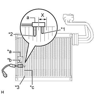
    E250743E01
  1. Install the No. 1 cooler thermistor as shown in the illustration.
    Part
    Length
    *a
    34.3 mm
    *b
    27.6 mm
    *c
    50 mm
    Text in Illustration 
    *1
    Sensor Part
    *2
    Fixed Part
    *3
    from Tank

    NOTICE:
    1. Be sure to insert the thermistor only once because reinserting it will not allow it to be firmly secured.
    2. When reusing the evaporator, insert the thermistor one row next to the one that has been used previously (X in the illustration).
    3. After inserting the thermistor, do not apply excessive force to the wire.
    4. Directly insert the thermistor until the edge of plastic case "a" comes into contact with evaporator "b".
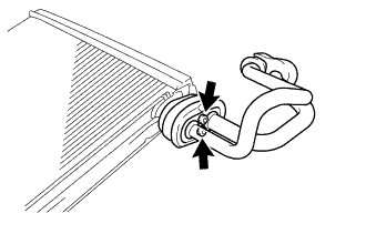
2. INSTALL AIR CONDITIONER TUBE ASSEMBLY


    E250774
  1. Using a 4 mm hexagon wrench, install the air conditioner tube assembly with the 2 hexagon bolts.

    Torque:
    3.5 N*m{ 36 kgf*cm , 31 in.*lbf }


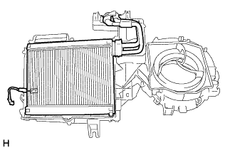
3. INSTALL NO. 1 COOLER EVAPORATOR SUB-ASSEMBLY


    E250759
  1. Install the No. 1 cooler evaporator sub-assembly with evaporator pipe as a unit.


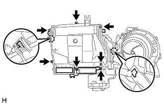
4. INSTALL COOLING UNIT CASE SUB-ASSEMBLY (for Automatic Air Conditioning System)


    E246468
  1. Engage the 2 claws.

  1. Install the cooling unit case sub-assembly with the 7 screws.


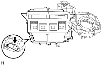
    E250758
  1. Engage the clamp.


5. INSTALL COOLING UNIT CASE SUB-ASSEMBLY (for Manual Air Conditioning System)

HINT:
Use the same procedure as for the automatic air conditioning system.


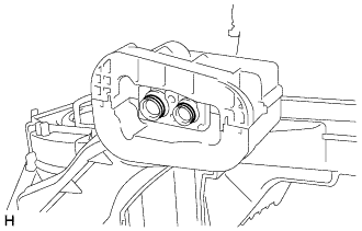
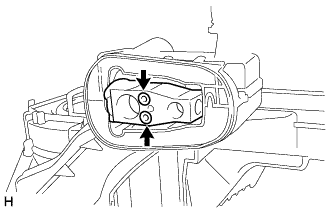
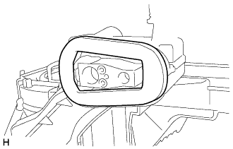
6. INSTALL COOLER EXPANSION VALVE


    E250766
  1. Sufficiently apply compressor oil to 2 new O-rings and the fitting surfaces. Install the 2 O-rings to the No. 1 cooler evaporator sub-assembly.

    Compressor oil:
    for HFC-134a (R134a):
    ND-OIL 8 or equivalent
    for HFO-1234yf (R1234yf):
    ND-OIL 12 or equivalent


    E250765
  1. Using a 4 mm hexagon wrench, install the cooler expansion valve with packing with the 2 hexagon bolts.

    Torque:
    3.5 N*m{ 36 kgf*cm , 31 in.*lbf }


    E250751
  1. Install the new gasket.


7. INSTALL HEATER CONTROL CABLE SUB-ASSEMBLY (for Manual Air Conditioning System)

NOTICE:
  1. When working, take care not to get dirt or dust in the gear grease.
  2. Do not hold gear sections while wearing cotton work gloves.


    E254919
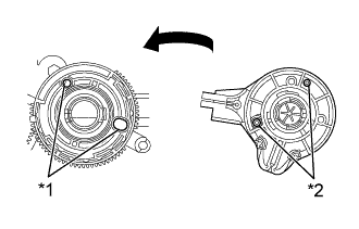
  1. Turn the pin on the cable side as far as possible in the direction of the arrow, and position it so that it matches the hole in the gear.

    HINT:
    Set the temperature adjustment dial to MAX HOT.


    E254922E01
  1. Hold the protrusion on the drive gear, and rotate the gear until the protrusion is aligned with the cylindrical section of the case.
    Text in Illustration 
    *1
    Drive gear hole
    *2
    Control cable positioning pin

    HINT:
    Temperature adjustment dial: MAX HOT

  1. Push the control cable positioning pin in slowly until it matches the drive gear hole, and install the heater control cable sub-assembly.


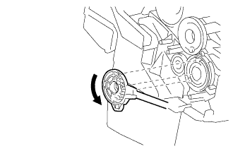
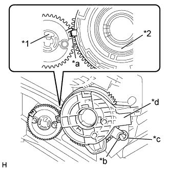
  1. Replacing the drive gear.


      E246474E01
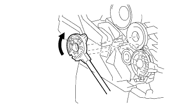
    1. When replacing the drive gear, pull the resin portion of the control cable forward slowly and remove it.
      Text in Illustration 
      *1
      Shaft Gear
      *2
      Drive Gear
      *a
      Reference Position
      *b
      Drive gear protrusion
      *c
      Cylindrical section of the case
      *d
      Resin portion of the control cable

      NOTICE:
      Do not pull the drive gear.

    2. Pull the drive gear forward slowly and remove it.

    3. Rotate the shaft gear clockwise slowly until it stops.

      NOTICE:
      Be sure not to turn too forcefully.

    4. Match the shaft gear and the drive gear with their specified positions, and insert the drive gear slowly into the heater case.


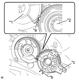
8. INSTALL AIR INLET DAMPER CONTROL CABLE SUB-ASSEMBLY (for Manual Air Conditioning System)

NOTICE:
  1. When working, take care not to get dirt or dust in the gear grease.
  2. Do not hold gear sections while wearing cotton work gloves.


    E254920
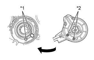
  1. Turn the pin on the cable side as far as possible in the direction of the arrow, and position it so that it matches the hole in the gear.

    HINT:
    Set the blower dial to FACE.


    E254921E01
  1. Hold the protrusion on the drive gear, and rotate the gear clockwise until it stops.
    Text in Illustration 
    *1
    Drive gear hole
    *2
    Control cable positioning pin

    HINT:
    Temperature control position: VENT

  1. Push the control cable positioning pin in slowly until it matches the drive gear hole, and install the air inlet damper control cable sub-assembly.


  1. Replacing the drive gear.


      E246472E01
    1. When replacing the drive gear, pull the resin portion of the control cable forward slowly and remove it.
      Text in Illustration 
      *1
      Mode Main Link
      *2
      Drive Gear
      *a
      Reference Position
      *b
      Drive gear protrusion
      *c
      Resin portion of the control cable

      NOTICE:
      Do not pull the drive gear.

    2. Pull the drive gear forward slowly and remove it.

    3. Match the mode main link and the drive gear with their specified positions, and insert the drive gear slowly into the heater case.


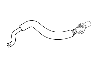
9. INSTALL ASPIRATOR PIPE (for Automatic Air Conditioning System)


    E250773
  1. Install the aspirator pipe.


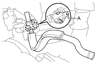
10. INSTALL ASPIRATOR (for Automatic Air Conditioning System)


    E250772E01
  1. Engage the 2 claws and align the section A with the case side pin, and then install the aspirator and aspirator pipe as one unit.


11. INSTALL AIR CONDITIONING UNIT ASSEMBLY (for Automatic Air Conditioning System)
(Click here)


12. INSTALL AIR CONDITIONING UNIT ASSEMBLY (for Manual Air Conditioning System)
(Click here)


13. CONNECT CABLE TO NEGATIVE BATTERY TERMINAL

Torque:
6.0 N*m{ 61 kgf*cm , 53 in.*lbf }


14. ADD ENGINE COOLANT

HINT:
Before replenishing the coolant, turn the A/C switch off. (w/ Air Conditioning System)

  1. Tighten the radiator drain cock plug.

  1. Pour in coolant of the specified density until it reaches the base of the entrance to the water inlet.

    HINT:
    1. The coolant contains anti-freeze and anti-rust agents for use with engines with aluminum cylinder blocks. Using other than the specified coolant may cause rust, so be sure to use Toyota SLLC 50 Blue.
    2. Crimp the inlet and outlet radiator hoses several times by hand, and add water if the water level in the entrance water inlet drops.
    3. The coolant quantity includes the quantity in the reserve tank.


    A279728
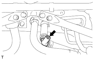
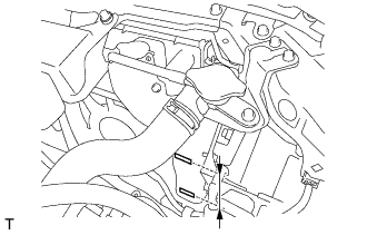
  1. Open the air bleed plug on the heater hose side. (for LHD)


    A279727
  1. Open the air bleed plug on the heater hose side. (for RHD)

  1. If the water level in the entrance to the water inlet drops, pour coolant in until it reaches the base of the entrance to the water inlet.

  1. Close the air bleed plug when the coolant begins to come out of the air bleed valve on the heater hose side.

  1. Pour in coolant of the specified concentration until it reaches the "FULL" level of the radiator reserve tank.

  1. Close the radiator cap. [*1]

  1. Start the engine, race it 5 to 6 times at under 3000 rpm or less, and then stop the engine. [*2]

    HINT:
    Finish this operation within 40 seconds.

  1. 1 minute after stopping the engine, remove the radiator cap and pour coolant in if the water level in the entrance to the water inlet has dropped. [*3]

  1. Repeat operations [*1], [*2], and [*3] until the water level in the entrance to the water inlet does not drop.

    HINT:
    Perform before the engine warms up, as the air that comes out of the inlet radiator hose will travel to the radiator side when the engine warms up and the thermostat opens.

  1. Close the radiator cap and the radiator reserve tank cap.

  1. Start the engine, set the heater on full warm, and then run it with the blower speed set to "LO".

  1. Run the engine at 2000 rpm or less until the radiator fan starts and stops. [*4]

    HINT:
    To prevent overheating, pay attention to the water temperature.

  1. Stop the engine and wait until the coolant temperature drops to 30 °C (86 °F) or less. [*5]

  1. Remove the radiator cap and, if the volume of coolant has dropped, pour coolant in until it reaches the base of the entrance to the water inlet and until it reaches the "FULL" level in the radiator reserve tank. [*6]

  1. Close the radiator cap. [*7]

  1. Set the heater to full warm, and, with the blower speed set to "LO", race the engine at 3000 rpm or less. [*8]

  1. At this point, if the engine coolant can be heard flowing in the heater core, repeat operations [*4], [*5], [*6], [*7], and [*8].


    A280287
  1. When the water level no longer drops, adjust the water level so that the water level in the radiator reserve tank reaches the "FULL" line.


15. CHARGE WITH REFRIGERANT
  1. for HFC-134a (R134a):

  1. for HFO-1234yf (R1234yf):


16. INSPECT FOR COOLANT LEAK

CAUTION:
Do not remove the radiator cap while the engine and radiator are still hot. Pressurized hot engine coolant and steam may be released and cause serious burns.

NOTICE:
Before performing each inspection, turn the A/C switch off.*

*: w/ Air Conditioning System


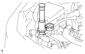
    A279737
  1. Fill the radiator with coolant and attach a radiator cap tester.

  1. Warm up the engine.

  1. Using a radiator cap tester, increase the pressure inside the radiator to 137 kPa (1.4 kgf/cm2, 20 psi), and check that the pressure does not drop.
    If the pressure drops, check the hoses, radiator and water pump for leaks. If no external leaks are found, check the heater core, cylinder block and cylinder head.


17. WARM UP ENGINE
  1. for HFC-134a (R134a):

  1. for HFO-1234yf (R1234yf):


18. INSPECT FOR REFRIGERANT LEAK
  1. for HFC-134a (R134a):

  1. for HFO-1234yf (R1234yf):


19. INSPECT SRS WARNING LIGHT