AIR CONDITIONING UNIT > INSTALLATION |
| 1. INSTALL AIR CONDITIONING UNIT ASSEMBLY (for Automatic Air Conditioning System) |
Install the 3 bolts and 3 nuts.
Engage the drain cooler hose.
Connect each connector and engage each clamp and install the air conditioning unit assembly.
| 2. INSTALL AIR CONDITIONING UNIT ASSEMBLY (for Manual Air Conditioning System) |
| 3. INSTALL AIR CONDITIONING UNIT ASSEMBLY (w/o Air Conditioning System) |
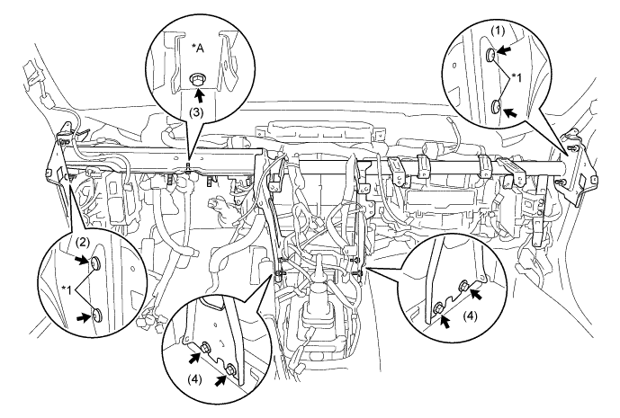
| 4. INSTALL INSTRUMENT PANEL REINFORCEMENT ASSEMBLY |
| *A | for RHD | - | - |
| *1 | "TORX" Bolt | - | - |
Using a 4 mm "TORX" wrench, install the 4 "TORX" Bolts in the order shown in the illustration.
Install the instrument panel reinforcement assembly with the 5 bolts in the order shown in the illustration.
Connect each connector and engage each clamp.
Connect the 2 earth wires with the 2 bolts.
| 5. INSTALL COWL SIDE TRIM BOARD LH |
Engage the 2 clips install the cowl side trim board LH.
Install the clip.
| 6. INSTALL COWL SIDE TRIM BOARD RH |
| 7. INSTALL FRONT DOOR SCUFF PLATE LH |
Engage the 6 claws install the front door scuff plate LH.
| 8. INSTALL FRONT DOOR SCUFF PLATE RH |
| 9. INSTALL STEERING COLUMN ASSEMBLY |
| 10. INSTALL LOWER NO. 1 INSTRUMENT PANEL AIR BAG ASSEMBLY (w/ Knee Airbag) |
Check that the ignition switch is off.
Check that the cable is disconnected from the negative (-) battery terminal.
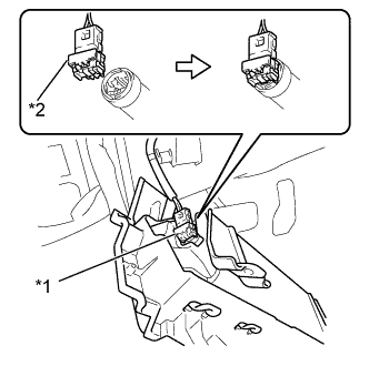 |
Connect the airbag connector to the lower No. 1 instrument panel airbag assembly.
| *1 | Airbag Connector |
| *2 | Airbag Connector Lock |
Push in the lock to install the airbag connector.
Install the lower No. 1 instrument panel airbag assembly with the 2 nuts.
| 11. INSTALL INSTRUMENT PANEL SUB-ASSEMBLY |
| 12. CONNECT AIR CONDITIONER TUBE AND ACCESSORY ASSEMBLY |
Remove the vinyl tape from the pipe.
Sufficiently apply compressor oil to a new O-ring and fitting surface of the air conditioner tube and accessory assembly.
Install the O-ring to the air conditioner tube and accessory assembly.
Install the air conditioner tube and accessory assembly.
| 13. CONNECT SUCTION HOSE SUB-ASSEMBLY |
Remove the vinyl tape from the pipe.
Sufficiently apply compressor oil to a new O-ring and the fitting surface of the suction hose sub-assembly.
Connect the O-ring to the suction hose sub-assembly.
Connect the suction hose sub-assembly.
Rotate the hook connector in the direction indicated by the arrow in the illustration.
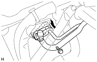 |
Insert the pipe joint into the cooler expansion valve securely and tighten the bolt.
| 14. CONNECT OUTLET HEATER WATER HOSE A |
Install the outlet heater water hose A and attach the clip.
| 15. CONNECT INLET HEATER WATER HOSE A |
Install the inlet heater water hose A and attach the clip.
| 16. CONNECT CABLE TO NEGATIVE BATTERY TERMINAL |
| 17. ADD ENGINE COOLANT |
Tighten the radiator drain cock plug.
Pour in coolant of the specified density until it reaches the base of the entrance to the water inlet.
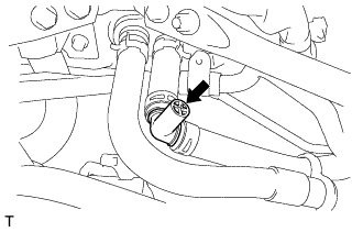 |
Open the air bleed plug on the heater hose side. (for LHD)
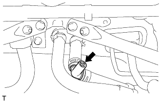 |
Open the air bleed plug on the heater hose side. (for RHD)
If the water level in the entrance to the water inlet drops, pour coolant in until it reaches the base of the entrance to the water inlet.
Close the air bleed plug when the coolant begins to come out of the air bleed valve on the heater hose side.
Pour in coolant of the specified concentration until it reaches the "FULL" level of the radiator reserve tank.
Close the radiator cap. [*1]
Start the engine, race it 5 to 6 times at under 3000 rpm or less, and then stop the engine. [*2]
1 minute after stopping the engine, remove the radiator cap and pour coolant in if the water level in the entrance to the water inlet has dropped. [*3]
Repeat operations [*1], [*2], and [*3] until the water level in the entrance to the water inlet does not drop.
Close the radiator cap and the radiator reserve tank cap.
Start the engine, set the heater on full warm, and then run it with the blower speed set to "LO".
Run the engine at 2000 rpm or less until the radiator fan starts and stops. [*4]
Stop the engine and wait until the coolant temperature drops to 30 °C (86 °F) or less. [*5]
Remove the radiator cap and, if the volume of coolant has dropped, pour coolant in until it reaches the base of the entrance to the water inlet and until it reaches the "FULL" level in the radiator reserve tank. [*6]
Close the radiator cap. [*7]
Set the heater to full warm, and, with the blower speed set to "LO", race the engine at 3000 rpm or less. [*8]
At this point, if the engine coolant can be heard flowing in the heater core, repeat operations [*4], [*5], [*6], [*7], and [*8].
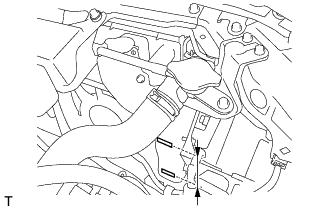 |
When the water level no longer drops, adjust the water level so that the water level in the radiator reserve tank reaches the "FULL" line.
| 18. CHARGE AIR CONDITIONING SYSTEM WITH REFRIGERANT |
for HFC-134a (R134a):
for HFO-1234yf (R1234yf):
| 19. INSPECT FOR COOLANT LEAK |
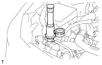 |
Fill the radiator with coolant and attach a radiator cap tester.
Warm up the engine.
Using a radiator cap tester, increase the pressure inside the radiator to 137 kPa (1.4 kgf/cm2, 20 psi), and check that the pressure does not drop.
If the pressure drops, check the hoses, radiator and water pump for leaks. If no external leaks are found, check the heater core, cylinder block and cylinder head.
| 20. WARM UP ENGINE |
for HFC-134a (R134a):
for HFO-1234yf (R1234yf):
| 21. INSPECT FOR REFRIGERANT LEAK |
for HFC-134a (R134a):
for HFO-1234yf (R1234yf):
| 22. INSPECT SRS WARNING LIGHT |