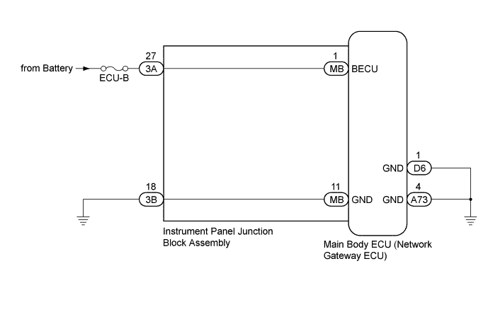
DTC B1012 Battery Power Supply Back Up Circuit |
| DTC No. | DTC Detection Condition | Trouble Area |
| B1012 | When BECU voltage is 8.3 V or less, or 16.7 V or more (BECU circuit malfunction) |
|
| 1.CLEAR DTC |
Clear the DTCs (Click here).
| NEXT | |
 |
| 2.CHECK FOR DTC |
Check for DTCs (Click here).
| Result | Proceed to |
| DTC B1012 is output | A |
| DTC is not output | B |
|
| ||||
| A | |
|
| 3.CHECK HARNESS AND CONNECTOR (BECU VOLTAGE) |
Disconnect the 3A instrument panel junction block assembly connector.
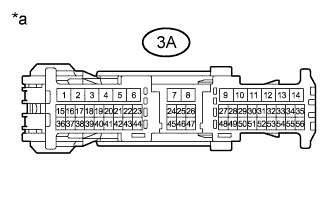 |
Measure the voltage according to the value(s) in the table below.
| Tester Connection | Condition | Specified Condition |
| 3A-27 - Body ground | Always | 11 to 14 V |
| *a | Front view of wire harness connector (to Instrument Panel Junction Block Assembly) |
|
| ||||
| OK | |
|
| 4.CHECK HARNESS AND CONNECTOR (ECU GROUND) |
Disconnect the D6 and A73 main body ECU (network gateway ECU) connector.
Disconnect the 3B instrument panel junction block assembly connector.
Measure the resistance according to the value(s) in the table below.
| Tester Connection | Condition | Specified Condition |
| D6-1 (GND) - Body ground | Always | Below 1 Ω |
| A73-4 (GND) - Body ground | Always | Below 1 Ω |
| 3B-18 - Body ground | Always | Below 1 Ω |
|
| ||||
| OK | |
|
| 5.INSPECT INSTRUMENT PANEL JUNCTION BLOCK ASSEMBLY |
Remove the instrument panel junction block assembly (Click here).
Remove the main body ECU (network gateway ECU) from the instrument panel junction block assembly.
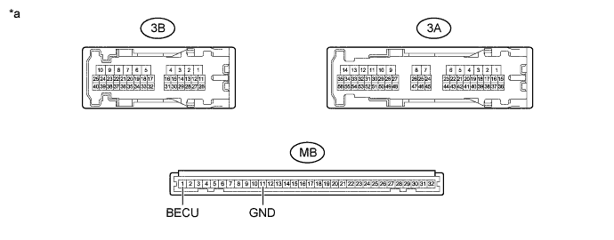
| *a | Component without harness connected (Instrument Panel Junction Block Assembly) | - | - |
Measure the resistance according to the value(s) in the table below.
| Tester Connection | Condition | Specified Condition |
| 3A-27 - MB-1 (BECU) | Always | Below 1 Ω |
| 3B-18 - MB-11 (GND) | Always | Below 1 Ω |
|
| ||||
| OK | ||
 | ||
| ||
