Home › Steering › STEERING COLUMN › STEERING WHEEL

STEERING WHEEL > INSTALLATION

for Preparation Click here


NOTICE:
  1. Do not replace the spiral cable with the battery connected and the ignition switch ON.
  2. Do not rotate the spiral cable without the steering wheel with the battery connected and the ignition switch ON.
  3. Ensure that the steering wheel is installed and aligned straight when inspecting the steering sensor.


1. INSTALL NO. 1 STEERING WHEEL ORNAMENT
  1. Engage the 2 claws and guide to install the No. 1 steering wheel ornament.


2. INSTALL LOWER STEERING WHEEL BOSS COVER (w/ Cruise Control System)
  1. Connect the cruise control main switch wire connector to the cruise control main switch assembly.

  1. Set the cruise control main switch assembly to the lower steering wheel cover.

  1. Engage the 2 claws and install the lower steering wheel cover.

  1. Install the 4 screws.

  1. Engage the clamp.


3. INSTALL LOWER STEERING WHEEL BOSS COVER (w/o Cruise Control System)
  1. Engage the 2 claws and install the lower steering wheel boss cover.

  1. Install the 2 screws.


4. INSTALL STEERING SHAKE DAMPER
  1. Install the steering shake damper with 2 screws to steering wheel assembly.


5. INSTALL SHIFT PADDLE SWITCH (TRANSMISSION SHIFT SWITCH ASSEMBLY) (for Automatic Transmission)
  1. Install the shift paddle switch (transmission shift switch assembly) with 4 screws.

    Torque:
    1.7 N*m{ 18 kgf*cm , 15 in.*lbf }

  1. Engage the clamp.


6. ALIGN FRONT WHEELS FACING STRAIGHT AHEAD


7. INSPECT AND ADJUST SPIRAL CABLE WITH SENSOR SUB-ASSEMBLY

NOTICE:
Do not adjust the spiral cable sub-assembly with the battery connected and the ignition switch ON.

  1. Check that the ignition switch is off.

  1. Check that the cable is disconnected from the negative (-) battery terminal.

    CAUTION:
    Wait at least 90 seconds after disconnecting the cable from the negative (-) battery terminal to disable the SRS system.

    NOTICE:
    The power window system utilizes a mechanism that the door glass moves down slightly when the door is opened, and that the glass moves up when closing the door in order to prevent the door molding from being damaged. When the battery negative (-) terminal needs to be disconnected for servicing, fully open the driver and passenger door glasses in advance.


    B311948E01
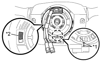
  1. Check if the spiral cable sub-assembly is centered.
    Text in Illustration 
    *1
    Matching Mark
    *2
    Colored Part

    HINT:
    When the spiral cable is attached in a central position, it will align with the matching mark, allowing the colored area indicated in the illustration to be checked.
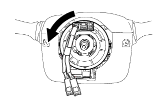
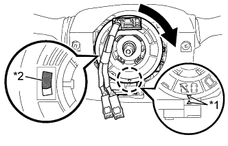
  1. If the spiral cable sub-assembly is not centered, center it.

    NOTICE:
    Do not turn the spiral cable sub-assembly using the airbag wire harness.


      B311952
    1. Rotate the spiral cable sub-assembly counterclockwise slowly by hand until it stops.


    2. B311989E01
    3. Rotate the spiral cable sub-assembly clockwise approximately 2.5 turns to the position where the matching mark is matched.
      Text in Illustration 
      *1
      Matching Mark
      *2
      Colored Part

      HINT:
      1. The spiral cable sub-assembly will rotate approximately 2.5 turns to both the left and right from the center.
      2. When centering is not possible, there may be an open circuit in the spiral cable. Replace the spiral cable and steering sensor with new ones.


8. INSTALL STEERING WHEEL ASSEMBLY


    C260489E01
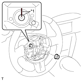
  1. Install the steering wheel assembly aligning the matchmarks on the steering wheel assembly and steering main shaft.
    Text in Illustration 
    *1
    Matchmark

  1. Install the steering wheel assembly set nut.

    Torque:
    39 N*m{ 398 kgf*cm , 29 ft.*lbf }

  1. Connect the connectors to the spiral cable sub-assembly and steering wheel assembly.


9. CHECK STEERING WHEEL CENTER POINT


10. INSTALL HORN BUTTON ASSEMBLY
  1. Check that the ignition switch is off.

  1. Check that the cable is disconnected from the negative (-) battery terminal.

    CAUTION:
    Wait at least 90 seconds after disconnecting the cable from the negative (-) battery terminal to disable the SRS system.

    NOTICE:
    The power window system utilizes a mechanism that the door glass moves down slightly when the door is opened, and that the glass moves up when closing the door in order to prevent the door molding from being damaged. When the battery negative (-) terminal needs to be disconnected for servicing, fully open the driver and passenger door glasses in advance.


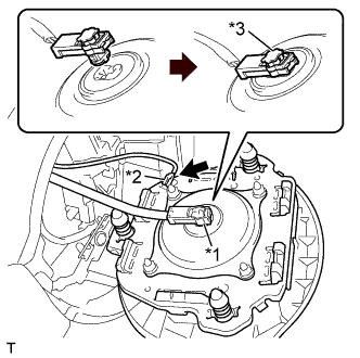
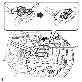
  1. for Dual Airbag System


      B311945E01
    1. Connect the 2 airbag connectors to the horn button assembly.
      Text in Illustration 
      *1
      Airbag Connector
      *2
      Horn Connector
      *3
      Airbag Connector Lock

      NOTICE:
      1. When connecting any airbag connector, take care not to damage the airbag wire harness.
      2. Be sure to only connect the connectors to each corresponding color.

    2. Push in the 2 locks to install the 2 airbag connectors.

    3. Connect the horn connector to the horn button assembly.


  1. for Single Airbag System


      B311353E01
    1. Connect the airbag connector to the horn button assembly.
      Text in Illustration 
      *1
      Airbag Connector
      *2
      Horn Connector
      *3
      Airbag Connector Lock

      NOTICE:
      When connecting any airbag connector, take care not to damage the airbag wire harness.

    2. Push in the lock to install the airbag connector.

    3. Connect the horn connector to the horn button assembly.


    B311354
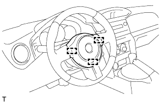
  1. Push the horn button assembly to engage the 3 pins carefully.

    NOTICE:
    1. Make sure that the pins are securely inserted into the steering holes.
    2. Make sure to engage the 2 upper pins first.
    3. Make sure that the horn button assembly is securely installed.


11. INSPECT HORN BUTTON ASSEMBLY
  1. Make sure that the horn sounds.
    If the horn does not sound, inspect the horn system (Click here).


12. PERFORM DIAGNOSTIC SYSTEM CHECK
(Click here)


13. INSPECT SRS WARNING LIGHT
(Click here)